Table of Contents
Advertisement
Quick Links
Advertisement
Table of Contents

Subscribe to Our Youtube Channel
Related Manuals for MPI TS200-SE


Summary of Contents for MPI TS200-SE
- Page 1 MPI TS200-SE 200 mm Manual Probe System User Manual...
- Page 3 Parts of this manual are subject to change without prior notice. We welcome any comments on ambiguities, errors, omissions, or missing pages. Never attempt any procedure on the MPI TS200-SE probe system that is not specially described in this manual. Unauthorized operation can cause faults or accidents. MPI Corporation is not liable for any problems resulting from unauthorized operation of the equipment.
- Page 4 You can also send e-mail to MPI Corporation using the web site.* • Other: If you purchased your MPI product from our distributors or representative, you can contact them for service and support.
-
Page 5: Table Of Contents
System Facility Hookup ........................18 Operation ���������������������������������������������������������������������������20 Chuck Stage ............................20 Microscope Movement ........................22 Platen Adjustment and Control ......................27 System Vacuum Control ........................28 MicroPositioner Setup and Control ....................29 Maintenance and Service �����������������������������������������������������35 Mechanical Adjustments ........................35 Preventive Maintenance ........................37 User Manual - MPI-TS200-SE-UG REV 1.1.0 -19122017... - Page 6 General Maintenance.........................37 Troubleshooting ........................38 Service ............................39 Facility Requirements ��������������������������������������������������� 40 User Manual - MPI-TS200-SE-UG REV 1.1.0 -19122017...
-
Page 7: Overview
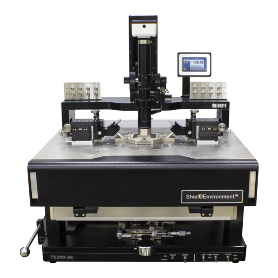
Overview The MPI TS200-ShieldEnvironment™ (TS200-SE) is designed to ensure advanced EMI/RFI/ light-tight shielding, ultra-low noise, low leakage measurement capabilities in a tempera- ture range from -60 to +300°C. TS200-SE Manual Probe System Front View with the Microscope Microscope Microscope movement... -
Page 8: Probe System Architecture
Probe System Architecture Microscope and Movement MPI TS200-SE microscope movement is mounted on top of the rigid microscope bridge. The bridge supports both 5050/8080 ZUM movement and 5050ZUM-VM pneumatic Z mo- vemnts with XY controlled knobs. Several microscope types are available and each has its own separate adapter. - Page 9 MicroPositioners which fit their operational familiarity thus providing immediately pro- ficiency. MPI unique MP80-DX with easy and precise definition down to 1μm - is the ideal choice for accurate and cost-effective multiline TRL – the only RF calibration method in the mmW and sub-THZ range.
-
Page 10: Non Electrical Utilities
Please connect the compressed air and vacuum supply to the system. If the probe system comes with accessories that require compressed air, nitrogen or vacuum, connect them as necessary. One grounding point can be found at the rear base platform of the TS200-SE manual probe system. Electrical Utilities MPI probe system may require power supply for the system accessories. -
Page 11: Installation
Installation Prior to the shipment of TS200-SE probe system, please refer to the facilities preparation sheet for the space and facilities requirement for the probe system. Contact a MPI service representative for more information. Probe System Unpacking Before unpacking TS200-SE probe system, inspect the wooden box(es) for evidence of damage or mishandling during shipping. -
Page 12: Probe System - Transport Locks Removal
Probe System - Transport Locks Removal MPI TS200-SE probe system moveable stages are secured by transport locks. All trans- port locks are in color with secure screws. Remove all transport locks with Allen Wrenches. Front View of TS200-SE with the Transport Locks. -
Page 13: Microscope Installation
Step 1: Mount the microscope onto the Microscope movement� On 50 x 50/80 x 80 ZUM/5050ZUM-VM Movement iMAG-M can be mounted on 5050/8080ZUM movemnent on TS200-SE. EZ10, SZ10 and MZ12 can be mounted on 5050ZUM-VM. The installation procedures of 50 x 50/80 x 80 ZUM/5050ZUM-VM Movement are similar. - Page 14 2. Connect the bracket of 5050ZUM/8080ZUM from step 1 as orange marks with an Allen Wrench and screws. 3. Connect the bracket as the orange mark and the bracke- ct of 5050ZUM/8080ZUM from step 2 with an Allen Wrench and screws. User Manual - MPI-TS200-SE-UG REV 1.1.0 -19122017...
- Page 15 5. Mount the top and rear cover and fix with an Allen Wrench and screws to finish the assembly. Option B: Mount EZ10, SZ10 and MZ12 on 5050ZUM-VM Movements on TS200-SE� SZ10 1. Hold the microscope and fix four mounting screws with an Allen Wrench to secure the microscope on 5050ZUM-VM Movement.
- Page 16 USB power supply. Connect the USB power supply to your facility power. Step 3: Install CCD camera 2MP to the microscope MZ12 Turn the CCD Camera 2MP clockwise to lock. User Manual - MPI-TS200-SE-UG REV 1.1.0 -19122017...
- Page 17 Turn the Mocticam 1080 clockwise when mounting onto the microscope and lock the rotation points by slotted screwdriver. Connect the HDMI, power cable and the USB dongle of the wireless mouse. Press the power button of Moticam 1080. User Manual - MPI-TS200-SE-UG REV 1.1.0 -19122017...
- Page 18 1.Turn the HDMI Camera MPI 1080 clockwise onto the microscope. SZ10 2.Fix the HDMI Camera MPI 1080 firmly onto the microscope with three points and an Allen Wrench. 3.Connect the SD card, HDMI, power cable and the USB dongle of the wireless mouse.
-
Page 19: System Facility Hookup
System Facility Hookup There are two built-in fittings of TS200-SE to be connected, behind the probe system, are the Vacuum and Air speed controller fittings. Hook up all of the facility fittings to complete the installation of the probe system. - Page 20 Ensure smooth, free movement over the complete surface and effective bra- king in X and Y Observe movement and braking in X and Y under the highest magnification. Make certain the image is clear. If necessary, adjust the leveling screw under the stage. User Manual - MPI-TS200-SE-UG REV 1.1.0 -19122017...
-
Page 21: Operation
Operation The operation of the MPI TS200-SE probe system is divided into five different sections, to include chuck stage, microscope movement, platen adjustment and control, system vacu- um control, and MicroPositioner Setup and Control. Chuck Stage Chuck stage control has X, Y, Chuck Theta control and Chuck Z fine movement by micro- meter and puck control to quickly move the wafer chuck. - Page 22 The puck control provides fast and large movement of XY stage of the chuck. Press the control knob to quickly move the chuck; release the control knob to lock the mo- vement of the chuck. Control Knob User Manual - MPI-TS200-SE-UG REV 1.1.0 -19122017...
-
Page 23: Microscope Movement
Microscope Movement MPI TS200-SE probe system can be configured with four microscopes and three movements. Microscopes: • MPI SuperZoom SZ10-10x Single tube microscope with USB LED Light Source • MPI MegaZoom MZ12-15x Single tube microscope with USB LED Light Source •... - Page 24 Turn the lock knob counterclockwise to unlock the Coarse Adjustment. Turn the lock knob clockwise to lock the Coarse Adjustment. Lock Course Height Adjustment Coarse Height Adjustment Fine Height Adjustment User Manual - MPI-TS200-SE-UG REV 1.1.0 -19122017...
- Page 25 25 mm first. 1. X Movement Control Knob 2. Y Movement Control 3. X Movement lock screw 4. Y Movement lock Screw 5. Thumb Screw 6. Manual Z Up Movement control knob User Manual - MPI-TS200-SE-UG REV 1.1.0 -19122017...
- Page 26 1 - SZ10 Magnification Adjustment 2 - MZ12 Magnification Adjustment Focus Adjustment Turn the coarse or fine height adjustment knob until the DUT is clear in the LCD mo- nitor. User Manual - MPI-TS200-SE-UG REV 1.1.0 -19122017...
- Page 27 8.5 x, the aperture dial should be around 5 is recommen- ded. 9. Pull the optical path switching lever to the right. The optical path switches to the ca- mera side, and you can see the image on the monitor. User Manual - MPI-TS200-SE-UG REV 1.1.0 -19122017...
-
Page 28: Platen Adjustment And Control
(300 µm), and loading (3 mm). The lift includes a safety lock rotation utility which prevents accidental platform descent. These features offer unparalleled functionality and are standard offerings for the MPI TS200-SE manual probe system. Prevention of unex- pected probe or wafer damage is critical to system design and provides intuitive control, accurate contact positioning, safe set-ups, and easy step and repeat functionality. -
Page 29: System Vacuum Control
System Vacuum Control Five vacuum ON/OFF switches located on the front-bottom panel of TS200-SE from right to left are Chuck, Aux Right and Left, Scope and CHUCK UP/DOWN. Switch on chuck vacu- um control when operating the wafer chuck and vice versa. Switch on left and right Auxili- ary Chucks to controls vacuum for the calibration substrates on the left and right auxiliary chucks. -
Page 30: Micropositioner Setup And Control
MicroPositioner Setup and Control All MPI MicroPositioners have magnetic base to create the extreme stable force when mounting the platen. Switch “ON” to mount it firmly onto the platen and switch “OFF” to remove it from the platen. XYZ Stage Movement Adjustment Turn the X stage movement control knob clockwise to move the X stage to the left;... - Page 31 45°and 60 °. turn to lock CAUTION Do not touch the insulation part with bare hands as it may cause conta- mination resulting in poor performance of the probe arm. User Manual - MPI-TS200-SE-UG REV 1.1.0 -19122017...
- Page 32 2. Fix the Kelvin arm onto the MicroPositioner with two screws and an Allen Wrench. Fix two screws 3.Load the MicroPositioner on the probe platen and connect the cables onto the Probe Arm Kelvin 50SE. User Manual - MPI-TS200-SE-UG REV 1.1.0 -19122017...
- Page 33 The two blue lines on the figure below are the screw locations of each MicroPositioner. MP60 MP50 MP40 MP25 3.One screw supplied to bolt the cable clamp(screwed location depends on the Left or Right version of the MicroPositioner you purchased). User Manual - MPI-TS200-SE-UG REV 1.1.0 -19122017...
- Page 34 5.Fix the probe on the RF Probe Arm by Allen Wrench and screws. The fine micro- meter screw is used for RF Probe planarity adjustment. 1.Fix RF Probe with Allen Wrench 2.RF Probe Planarity adjustment 6.Install RF Cable and tighten the connector onto the RF probe. User Manual - MPI-TS200-SE-UG REV 1.1.0 -19122017...
- Page 35 Two cable cap sizes are allowed to adjust. When the RF cable is not in use, turn the ad- just ring of the cable cap to full. 8.Fix the ShielDcap by tightening four thumb screws to secure the ShielDEnviron- ment Tighten thumb screws User Manual - MPI-TS200-SE-UG REV 1.1.0 -19122017...
-
Page 36: Maintenance And Service
These adjustment procedures ensure system accuracy and reliability. Wafer Chuck Planarization Procedure NOTE Wafer chuck planarization should be performed by a MPI service repre- sentative. Wafer chuck planarization ensures equal probe contact force from tip-to-tip of probes and throughout the wafer chuck range of travel. The wafer chuck is planarized at the fac- tory, but adjustment may be required at installation. - Page 37 Step 3: After the wafer chuck planarization reaches the criterion, tighten the screw point to fix the wafer chuck planarization. Step 4: Repeat step 1 to step 3 to execute wafer chuck planarization of the last test point. User Manual - MPI-TS200-SE-UG REV 1.1.0 -19122017...
-
Page 38: Preventive Maintenance
Preventive Maintenance The TS200-SE requires minimal preventive maintenance. Take care to keep the system clean and covered when not in use. The following cleaning and lubrication procedures should be performed at the recommended intervals. -
Page 39: Troubleshooting
Attempting to troubleshoot beyond the instructions in this section may cause further damage to the probe station or related equipment, and may also void the station warranty. User Manual - MPI-TS200-SE-UG REV 1.1.0 -19122017... -
Page 40: Service
Repacking To retain the validity of the warranty, always use the original packing materials. Cont- act a MPI representative for replacement shipping materials or hardware. Remove all probes and accessories from the probe system, including the microscope. Do not ship them unless they are associated with the failure symptoms. -
Page 41: Facility Requirements
1060 mm (W) x 1150 mm (D) x 800 mm (H) / 186 kg Box(approx. values) Dimension and Weight Probe station+ Vibra- (approx. tion Isolation Table 1670 mm (W) x 1585 mm (D) x 1655 mm (H) / 360 kg values) (approx. values) User Manual - MPI-TS200-SE-UG REV 1.1.0 -19122017... - Page 42 Keyboard / Mouse Tray Included Front Protection Bar Castors Included Shelves Included Upper and Lower Accessories Accepted Monitor Stand(s) and Instrument Shelf Weight Approx. 210 kg ( 463 lb.) Approx. 210 kg ( 463 lb.) User Manual - MPI-TS200-SE-UG REV 1.1.0 -19122017...
Need help?
Do you have a question about the TS200-SE and is the answer not in the manual?
Questions and answers