
Related Manuals for MPI EchoBed X


Summary of Contents for MPI EchoBed X
- Page 1 Owner’s Manual EchoBed® X VasScan Table™ X Owner _____________________ Model _____________________ Serial # _____________________ Date _____________________ Echo/Vascular User Manual (15381-C) Page 1 of 46 DCR-00172...
-
Page 2: Table Of Contents
Table of Contents Symbols and Definitions ..............3 Safety Warnings & Cautions..............5 Intended Use ..................7 Safety Features ................... 7 Set Up ....................8 Transport Position................8 Product Illustration ................9 Controls and Indicators ..............10 Use Instructions ................. 14 Powering the Product .............. - Page 3 Symbols and Definitions Warning, follow instructions for use. Failure to comply may result in injury. Warning, sitting is prohibited. Failure to comply may result in injury. Warning, standing is prohibited. Failure to comply may result in injury. Applied Part complying with specified requirements IEC 60601-1 to provide protection against electric shock, particularly regarding allowable patient leakage current.
- Page 4 Symbols and Definitions Maximum Patient Weight. Indicates the maximum patient weight that may be placed on the product. Safe Working Load. Indicates the sum of the patient weight and accessories that may be placed on the product. WARNING / CAUTION / NOTE Definition The words WARNING, CAUTION, and NOTE carry special meanings and should be carefully reviewed.
-
Page 5: Safety Warnings & Cautions
Safety Warnings & Cautions WARNING: Obey these safety instructions to help prevent injury and/or equipment damage: • Read and understand all warnings in this manual and on the unit itself prior to use with a patient. • The device should be operated by trained persons only. •... - Page 6 Safety Warnings & Cautions • Verify the area around the product is free of impediments before operating to prevent injury or equipment damage. • Keep hands and feet clear from beneath the patient surface when lowering surface height or making positioning adjustments in order to avoid possible injury.
-
Page 7: Intended Use
Intended Use This product is intended to be used in an environment where ultrasound and other such diagnostic equipment is present, including hospitals, outpatient facilities, and doctor’s offices. The product is intended to be used by trained healthcare professionals who possess the ability to operate the product safely. -
Page 8: Set Up
Set Up The product has been shipped to you in “plug and play” condition. After unpacking the product, we recommend performing an initial test of your product to ensure that each function is in correct working order. After reviewing this manual you are ready to begin using your product. -
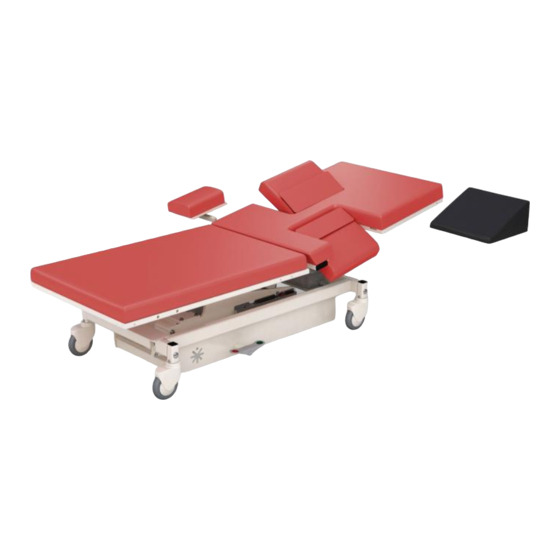
Page 9: Product Illustration
Product Illustration *Optional features may be shown Echo/Vascular User Manual (15381-C) Page 9 of 46 DCR-00172... -
Page 10: Controls And Indicators
Controls and Indicators Unique Device Identification Label • Serial # • Item # • Item Description • Unique Identifier Certification Label Refer to Manual Label Echo/Vascular User Manual (15381-C) Page 10 of 46 DCR-00172... - Page 11 Controls and Indicators No Sitting label Hand Control Note: Hand control functions will vary depending on the model purchased. Your hand control may differ from the images to the right. Echo/Vascular User Manual (15381-C) Page 11 of 46 DCR-00172...
- Page 12 Controls and Indicators AC Input Battery Pedals for Single Pedal Brake Side Rail Release Echo/Vascular User Manual (15381-C) Page 12 of 46 DCR-00172...
- Page 13 Controls and Indicators Drop Section Release Drop Section Remote Release Back Rest Release Echo/Vascular User Manual (15381-C) Page 13 of 46 DCR-00172...
-
Page 14: Use Instructions
Use Instructions Powering the Product The product can be powered by AC power from a wall outlet or by DC power via the optional battery. The product is “on” whenever it is plugged into AC power or when a charged battery is installed. The product should not be positioned in a way that would make it difficult to remove power by unplugging the AC power cord or removing the battery. -
Page 15: Locking The Casters
Use Instructions Locking the Casters The product may be equipped with total locking casters or individual locking casters. The total locking casters have 3 functional positions: full swivel, steer, and full lock. • In the neutral position all four casters may swivel and roll. •... -
Page 16: Hand Control Functions
Use Instructions Hand Control Functions Hand control functions will vary depending on the model purchased. Your hand control may not include all of the functions listed below. Adjusting Surface Height The minimum surface height is 19” when the surface is level but will stop at heights above this value depending on the angle of Trendelenburg or Reverse Trendelenburg. -
Page 17: Memory Function
Use Instructions Memory Function Some product configurations have the ability for the user to set memory positions. The control box can store two unique positions for buttons P1 and P2. The memory feature stores the position for height, fowler, and trend. To set a memory position, press and hold the “M”... -
Page 18: Under-Bed Lights
Use Instructions Under-bed Lights The product may be equipped with optional under-bed lights. Press both height up-down buttons to turn on/off the under-bed lights. WARNING • Verify the area around the product is free of impediments before operating to prevent injury or equipment damage. -
Page 19: Using The Vasscan Table™ X Foot Rest
Use Instructions Using the VasScan Table™ X Foot Rest The VasScan Table™ X is equipped with a foot rest used during procedures requiring a reverse Trendelenburg position. The foot rest plugs into the receiving block located on the stationary section. The foot rest height can be adjusted by approximately 3”... - Page 20 Use Instructions Using the Imaging Drop Section The imaging drop section is located on the fowler section to allow ergonomic sonographer access to the patient. Location of Imaging Drop Section To open the drop section, pull the handle to release drop section latches. Use the remote release located on the opposite side of the support surface.
- Page 21 Use Instructions Using the Sonographer Drop Sections The sonographer drop section allows right handed scanners to get closer to the patient. It can also be adjusted to act as a patient back rest. To use the sonographer drop section as a back rest pull up on the drop section until it locks into position.
-
Page 22: Using The Carotid Head Rest
Use Instructions Using the Carotid Head Rest The product may be equipped with an optional head support to provide better access during carotid artery scanning. Prior to using the head support the mounting brackets must be installed at the head end of the product. The head rest mount is located underneath the head end of the fowler section. -
Page 23: Using The Side Rails
Use Instructions Using the Side Rails The product may be equipped with optional side rails. The side rail brackets are stored under the support surface when not in use and are pulled out to attach the side rails. The side rails may be oriented in multiple directions depending on the access required for the procedure. -
Page 24: Using The Sonographer Extension
Use Instructions Using the Sonographer Extension The product may be equipped with an optional sonographer seat extension. This seat extension allows for a larger seating area for right handed sonographers. The sonographer seat extension bracket is stored under the support surface when not in use and is pulled out to attach the sonographer’s extension. -
Page 25: Foley Bag Clip
Use Instructions Foley Bag Clip The product may be equipped with a hook for hanging a Foley bag. Storing the Hand Control The hand control may be hung on the hook located underneath the support surface. The hook may be moved to the end user’s preference. -
Page 26: Iv Pole And Holder
Use Instructions IV Pole and Holder The product may be equipped with an IV pole. Place the IV pole into the mounting bracket and tighten the knob to secure the IV pole to the product. The mounting bracket may be located approximately in the locations shown. -
Page 27: Positioning Wedge
Use Instructions Positioning Wedge The positioning wedge may be used to support the patient at a desired angle. Pediatric Adaptor The product may be used with a pediatric/geriatric adaptor. To install use the following steps: 1. Lower the Drop Section 2. -
Page 28: Preventative Maintenance
Preventative Maintenance The following Preventative Maintenance should be performed at a minimum annually. If any of these checks fail, repair or replace the part as applicable. • Visually inspect all mechanical assemblies and moving parts on the product ensuring smooth, steady operation. •... -
Page 29: Expected Life
Expected Life The expected life of the product is 7 years of normal use. Some components may have a shorter life and require replacement. Note: See Warranty section for warranty information. Discard the Unit Upon reaching the end of its useful life the product may be discarded in accordance with local and federal standards. -
Page 30: Cleaning
Cleaning Plastic and Painted Surfaces The painted metal and plastic surfaces can be cleaned with normal cleaners and disinfectant. STEP ACTION Clean and/or disinfect with liquid cleaner of choice being careful to follow label instructions provided with cleaner. (Always test a small area first to determine suitability of solution) Wipe the surface clean with a damp cloth after applying cleaners and disinfectant to remove excess residue buildup. - Page 31 Cleaning RECOMMENDED MAXIMUM CLEANER TO WATER SOLUTIONS 1:1 mix of mild soap and water. Wipe surface with damp cloth with Mildest water only after cleaning. Straight application of common disinfectants. Wipe surface with damp cloth with water only after cleaning. 1:1 mix of ammonia and water.
-
Page 32: Service Calls
Service Calls A “Troubleshooting Guide” is included to instruct you in the event of a malfunction. If you are experiencing any of the following symptoms, this guide may help you quickly solve the problem. If, after consulting this guide, you are still unable to operate your product please contact Medical Positioning at 1-800-593-3246. -
Page 33: Troubleshooting Guide
Troubleshooting Guide SYMPTOM PROBABLE CAUSE SUGGESTION • • Power cord not plugged all Push power cord securely the way into wall receptacle. into receptacle. • Check power availability or • Power outlet receptacle not plug unit into another supplying 120 VAC power. receptacle. -
Page 34: Specifications
Specifications Product Models & Attributes Depending on the country of sale and the options chosen the model number may be slightly different than what is shown below. For example, the model number may be followed by a country code such as 201UK or 201EU. Additionally the model number may be followed by an option code such as 201UK-A or 201-A. - Page 35 Specifications VasScan Table™ X ATTRIBUTE Base Width 26” 26” Base Length 48.5” 48.5” Surface Width 28” 28” Surface Length 80.5” 80.5” Surface Height Range 19” – 38” 19” – 38” *To top of cushion Trendelenburg/ 15° / 30° 15° / 30° Reverse Trendelenburg Fowler Range 0°...
- Page 36 Specifications Environmental Conditions Range for Storage and ATTRIBUTE Range for Use Transport Ambient Temperature +0° to 40° C -10° to +50° C 20% to 90% @ 30°C – 20% to 90% @ 30°C – Relative Humidity not condensing not condensing Atmospheric Pressure 860 to 1060 hPa 860 to 1060 hPa...
- Page 37 Specifications Classifications and Standards ATTRIBUTE SPECIFICATION • IEC 60601-1:2005 + A1:2012 • ANSI/AAMI ES60601-1:2005/(R)2012 and A1:2012, C1:2009/(R)2012 and A2:2010/(R)2012 • CAN/CSA-C22.2 NO. 60601-1:14 Standards • EN 60601-1:2006 +A11:2011 +A1:2013 +AC:2014 • IEC 60601-1-2:2007 • EN/ISO 14971:2012 • Class I equipment Protection against •...
- Page 38 Specifications Applied Parts (in accordance with IEC 60601-1) • All padded surfaces • Arm rests • Foot rest • Straps Electromagnetic Emissions Guidance The product use components that meet the requirements for IEC 60601-1-2. Other products that are used in the vicinity of the this product should also comply with this standard.
- Page 39 Specifications Electromagnetic Compatibility Medical electrical equipment needs special precautions regarding electromagnetic compatibility (EMC) and needs to be installed and put into service according to the EMC information provided in this user manual. Portable and mobile radio frequency (RF) communications equipment can affect medical electrical equipment.
- Page 40 Specifications Guidance and Manufacturer's Declaration - Electromagnetic Immunity The product is intended for use in the electromagnetic environments specified below. The customer or the user of the product should assure it is used in such an environment. Immunity IEC 60601 Compliance Level Guidance Test...
- Page 41 Specifications Guidance and Manufacturer's Declaration - Electromagnetic Immunity The product is intended for use in the electromagnetic environments specified below. The customer or the user of the product should assure it is used in such an environment. Immunity IEC 60601 Compliance Guidance Test...
- Page 42 Specifications Recommended separation distances between portable and mobile RF communications equipment and the MPI Echo/Vascular Products The product is intended for use in an electromagnetic environment in which radiated RF disturbances are controlled. The customer or the user of the product can help prevent electromagnetic interference by...
- Page 43 Specifications Standard and Optional Configurations EchoBed® X VasScan Table™ X ATTRIBUTE STANDARD OPTIONAL STANDARD OPTIONAL Hand control Side Rails Single Pedal Brake/Mobility Paper Roll Holder Positioning Wedge Sonographer Extension 1 Function Foot Control 3 Function Foot Control IV Pole & Holder Battery Functionality 2nd Battery &...
- Page 44 Specifications Replacement Parts and Upgrade Kits The following items are replacements parts or upgrade kits for the EchoBed® X and VasScan Table™ X. Some of the items below may not be suitable for all models of product. Part Description Part # Hand Control See Note Below 1 Function Foot Control...
-
Page 45: Warranty
MPI. MPI makes no other warranty, either expressed or implied, with respect to this product. MPI specifically disclaims the implied warranties of merchantability and fitness for a particular purpose. - Page 46 MPI. MPI makes no other warranty, either expressed or implied, with respect to this product. MPI specifically disclaims the implied warranties of merchantability and fitness for a particular purpose.
Need help?
Do you have a question about the EchoBed X and is the answer not in the manual?
Questions and answers