Table of Contents
Advertisement
Advertisement
Table of Contents

Related Manuals for INVISIBLE FENCE Doorman


Summary of Contents for INVISIBLE FENCE Doorman
- Page 1 ® Invisible Fence Brand Doorman™ Pet Door Installation and Setup Instruction Doorman™ Electronic Pet Door Smart Doorman™ Electronic Pet Door ® BOUNDARY PLUS DOORMAN KIT RAC00-17200 BOUNDARY PLUS DOORMAN MODULE RAC00-17201 ™ BOUNDARY PLUS SMART DOORMAN MODULE RAC00-17202 March 2021...
-
Page 2: Table Of Contents
Preparing and Cutting the Door ..................... 12 4.2.4 Mounting the Kit in a Door ....................18 4.2.5 Operating the Smart Doorman on AC Power with Battery Backup ........22 2 of 22 U:\My Documents\Invisible Fence\Field Testing\Boundary Plus 2.0\Doorman\210318co Doorman Install Manual.docx... -
Page 3: Introduction
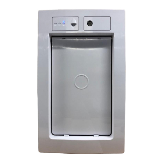
Frame/Flap system) with replaceable Doorman and Smart Doorman electronics modules. 2.1.1 RAC00-17200 BOUNDARY PLUS DOORMAN KIT Image 1 below shows all parts included in the Boundary Plus Doorman Kit. The kit includes a replaceable door flap and a serviceable/replaceable locking mechanism. This kit will be used for all installs. -
Page 4: Rac00-17201 Boundary Plus ® Doorman Module
DOORMAN MODULE Image 2 below shows all parts included with the Boundary Plus Doorman Module. This SKU should be selected for an 800/BP Doorman replacement or new install. These are the same electronics that are in the current Doorman assembly. -
Page 5: Setup And Operation Instructions
1. Insert the PIR sensor plug into the opening and secure with the two screws enclosed. 2. Snap the bottom two lugs of the Module into the bottom two catches on the Doorman Kit frame. Ensure the Locking Mechanism wire harness is fed under the module. -
Page 6: Rac00-17200 And Rac00-17202 (Smart Doorman)
Unpackage the Boundary Plus Doorman Kit and the Boundary Plus Doorman Module. 1. Snap the bottom two lugs of the Module into the bottom two catches on the Doorman Kit frame. Ensure the Locking Mechanism wire harness is fed under the module. -
Page 7: Boundary Plus Smart ™ Doorman Electronic Pet Door Setup
Setup for the Boundary Plus Smart Doorman Electronic Pet Door is similar to any other device of the Smart System. Follow the instructions below to set up the Smart Doorman to work in a system with a ® Smart Computer Collar receiver. - Page 8 ® Invisible Fence Brand Doorman™ Pet Door Installation and Setup Instruction Image 7 Image 8 Image 9 8 of 22 U:\My Documents\Invisible Fence\Field Testing\Boundary Plus 2.0\Doorman\210318co Doorman Install Manual.docx...
- Page 9 3.2.2.3 Set Up Computer Collar receiver to Operate with Doorman Follow the steps below to set up a Computer Collar to work with a Smart Doorman. Image 10 1. Return to the Technician App main page i. Search Customer again (this brings any new information into the App) (1) ii.
-
Page 10: Installation
4 Installation Test Operation Prior to any Doorman installation, test the operation of the Doorman inside and outside of where the door will be installed. Testing the door operation at the installation location, inside and out, will ensure fewer opportunities of issues occurring once the door is installed. -
Page 11: Preparation
Mark 4.125” down from the inside top edge. This mark should be scribed into the aluminum since marker will wear away over time. 4.125 ” Image 13 11 of 22 U:\My Documents\Invisible Fence\Field Testing\Boundary Plus 2.0\Doorman\210318co Doorman Install Manual.docx... -
Page 12: Measure The Pet
1. With the door still on the hinges: a. Determine where the Doorman will go. A door should not be cut any closer than 3 inches from the edge. To make this easy, the template material is 3 inches wide. Ensure the main area of the template does not overhang the door. - Page 13 Brand Doorman™ Pet Door Installation and Setup Instruction d. Check to make sure the door is plumb. A door that is not plumb may cause the Doorman to look unlevel or to perform poorly. Image 16 2. Remove the door from the hinges using a hammer, punch/nail and pliers.
- Page 14 4. Secure the template to the door with the three clamps. Use wood or metal blocks on the bottom side of door to spread the clamping load and not damage the door. Image 19 14 of 22 U:\My Documents\Invisible Fence\Field Testing\Boundary Plus 2.0\Doorman\210318co Doorman Install Manual.docx...
- Page 15 (ifdealersupply.com) ½” ½” ≤ Router Bushing Image 20 6. Place the router in all four corners and plunge completely through the door Bottom Side Corner Plunge Image 21 15 of 22 U:\My Documents\Invisible Fence\Field Testing\Boundary Plus 2.0\Doorman\210318co Doorman Install Manual.docx...
- Page 16 NOTE: Moving the router counterclockwise around the template will cause the router bit to drift away from the template. Moving too fast or an incorrect router RPM may cause bits to break. Image 23 16 of 22 U:\My Documents\Invisible Fence\Field Testing\Boundary Plus 2.0\Doorman\210318co Doorman Install Manual.docx...
- Page 17 When complete, make a second pass to clean up any edges. Remove cutout. Image 25 11. The door can be placed back on the hinges. 17 of 22 U:\My Documents\Invisible Fence\Field Testing\Boundary Plus 2.0\Doorman\210318co Doorman Install Manual.docx...
-
Page 18: Mounting The Kit In A Door
Unpackage the Doorman Kit. Install the preferred electronics before or after mounting the Doorman. Cut the door in any method currently used for Doorman and rehang the door if it was removed to cut the hole. 1. The door kit can be mounted with the flap in or out. It is easier to hold pieces together when the flap is removed. - Page 19 #6-18 x 2” to secure the kit to the door. DO NOT over tighten the six screws, especially the center two. Image 29 19 of 22 U:\My Documents\Invisible Fence\Field Testing\Boundary Plus 2.0\Doorman\210318co Doorman Install Manual.docx...
- Page 20 There are two snap at the top of the frame and one snap to either side. Slots in kit Hooks in frame Image 31 Image 32 20 of 22 U:\My Documents\Invisible Fence\Field Testing\Boundary Plus 2.0\Doorman\210318co Doorman Install Manual.docx...
- Page 21 7. Caulk the outside of the door between the kit and the frame and the frame and the door. Do not caulk bottom edge of exterior frame. Image 33 21 of 22 U:\My Documents\Invisible Fence\Field Testing\Boundary Plus 2.0\Doorman\210318co Doorman Install Manual.docx...
-
Page 22: Operating The Smart Doorman On Ac Power With Battery Backup
4.2.5 Operating the Smart Doorman on AC Power with Battery Backup The Smart Doorman is designed to operate with a GPS Mobile Battery (RIF00-15980) as the primary power source, however, it can also be powered with an Indoor Avoidance Power Adapter, RAC00-13701.
Need help?
Do you have a question about the Doorman and is the answer not in the manual?
Questions and answers
Do you have updated doors? We just have the door with the auto- lock or unlock option but are there Bluetooth options out now?
Yes, the INVISIBLE FENCE Doorman door supports Bluetooth options through the use of a Large Bluetooth Program Tool (RIF00-16436) which is used to connect and configure the Doorman.
This answer is automatically generated