
Related Manuals for Kyoeisha Baroness LM315GC


Summary of Contents for Kyoeisha Baroness LM315GC
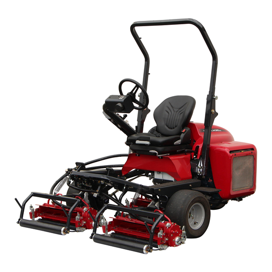
- Page 1 Triple Greens Mower LM315GC [BRUSH, CR] Assembly and installation manual 乗用3連グリーンモア LM315GC [CRブラシ]取扱要領書 Vol.1.1 Serial No.#30001~...
- Page 2 The information described in this manual is subject to change without prior notice for improvement. When replacing parts, be sure to use genuine Baroness parts or parts designated by Kyoeisha. Note that the Baroness product warranty may not apply to defects caused by the use of parts from other companies.
- Page 3 This symbol is accompanied by the word "Danger," "Warning," or "Caution." All labels with this symbol describe important safety precautions, so please read such labels carefully and only operate the machine after you have understood them completely. Failure to adequately follow these safety precautions may cause an accident.
- Page 4 When installing, removing, and adjusting optional equipment and attachments, observe the following safety instructions to ensure safe operation. オプション、アタッチメントの取付け、取外し、及び調整をするときは、以下の安全指示に従い、安全作業を 行ってください。 Before installation, removal, adjustments, etc., park the machine on a level surface. Set the parking brake, stop the engine, and remove the key. Ensure that all the parts have come to a complete stop. Keep your hands and feet away from moving parts.
- Page 5 Installing Optional Equipment for the LM315GC LM315GC オプション取付要領 BRUSH, CR CR ブラシ Intended use: The rotating brush prevents grass clippings, etc., from becoming attached to the rear roller. 用途;回転するブラシにより、後ローラーに刈芝などが付着することを防止します。 Check that all parts are included. The following parts are included in the package. Should any part be missing or damaged, please contact the dealer you purchased it from.
- Page 6 BELT, FLEXSTAR 10-FL-355 HOUSING COMP, BRUSH BRUSH COMP, ROLLER ブラシハウジング Comp ローラーブラシ Comp フレックススターベルト 10-FL-355 LM315R-1317Z0 Qty:3 Qty:3 Qty:3 PIN, JOINT 5.2-18 NUT, WITH F-RING, M5 COVER COMP, CR BRUSH BELT 5.2 ジョイントピン 18 5U ナット CR ブラシベルトカバーComp LM315GC7613Z8 K0144050002 Qty:3 Qty:3 Qty:3...
- Page 7 Tightening torque 締付トルク Appropriate tightening torque [General bolts Strength class: 4.8 Required tightening torque Nominal diameter 適正締付トルク【一般ボルト 強度区分 4.8】 必要な締付トルク 呼び径 kgf-cm lb-in ○ 30.59~50.99 26.55~44.26 ○ 71.38~91.77 61.96~79.66 ○ 14~19 142.76~193.74 123.91~168.17 ○ 29~38 295.71~387.49 256.68~336.34 When tightening bolts, refer to the above table. We will not be held responsible for any damage resulting from improper or excessive tightening, etc.
- Page 8 Installing the BRUSH, CR CR ブラシの取付手順 Steps Illustrations Descriptions 手順 図 説明 Using a hex key (A), remove the bolts (B) and conical disc spring (C). (Three locations) Do not remove the retaining housing plate (4) since it will be used. If the groomer kit has not yet been installed, install the retaining housing plate (4) onto the fulcrum metal (D).
- Page 9 Steps Illustrations Descriptions 手順 図 説明 Pass the brush housing (8) through the rear roller bracket (A) on the right side, and then temporarily tighten it with the washer (B), spring washer (C) and small nut M20 (D). 右側の後ローラーブラケット(A)にブラシハウジング (8)を通し、ワッシャ(B)、さらばね座金(C)、20 小型ナ ット(D)で仮締めしてください。...
- Page 10 Steps Illustrations Descriptions 手順 図 説明 While checking that the retaining housing plate (4), brush frame, tension pulley mounting adjuster (D) and fulcrum metal of CR brush (5) are correctly in place, use a hex key (A) to alternately tighten the three bolts (B). After tightening the bolts, check that the tension pulley mounting adjuster (D) moves.
- Page 11 Steps Illustrations Descriptions 手順 図 説明 Lower the tension pulley (A) in the opposite direction of the white arrow, and then install the Flexstar belt (7). Push the area of the Flexstar belt (7) indicated by the black arrow. Lift up the tension pulley (A) in the direction of the white arrow so that the lower section of the Flexstar belt (7) is 3 - 5 mm below the upper section.
- Page 12 Head Office 1-26, Miyuki-cho, Toyokawa, Tel : (0533) 84 - 1390 Fax : (0533) 89 - 3623 Aichi-Pref. 442-8530 Japan. 442 - 8530 TEL (0533) 84 - 1221 1 - 26 FAX (0533) 84 - 1220 LM315GC-AM01GBA/16B-00-KES...
Need help?
Do you have a question about the Baroness LM315GC and is the answer not in the manual?
Questions and answers