Kyoeisha Baroness LM531 Service Manual
Hide thumbs
Also See for Baroness LM531:
- Owner's operating manual (91 pages) ,
- Owner's operating manual (125 pages)

Related Manuals for Kyoeisha Baroness LM531


Summary of Contents for Kyoeisha Baroness LM531
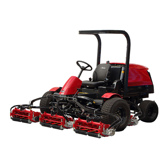
- Page 1 Technical docuentation No.TD-LM531-008-02 5-Unit Reel Mower Service Manual Serial No. LM531:10001- Ver.1.0...
- Page 2 Items of description are categorized per system for representative maintenance contents. We hope you will use the product safely, and take advantage of its best performance. Kyoeisha Co., Ltd. Warning Symbols This manual uses the following warning symbols for handling precautions that are important for your safety.
- Page 3 Engine ・ Hydraulic equipment ・ For repair of those items, please contact your sales dealer or Kyoeisha. Please note that our product warranty may be void if you disassemble or repair the items.
- Page 4 LM531 Introduction...
-
Page 5: Table Of Contents
LM531 Contents Safety .............. Page 1-1 Maintenance Schedule ........Page 8-3 List of Consumables ........Page 8-8 Safe Operating Practices .......Page 1-2 Safety Signs and Instruction Signs ....Page 1-5 Disposal ............Page 2-1 Recycle and Waste Disposal ......Page 2-2 Maintenance Standards and Maintenance .. - Page 6 LM531 Contents...
-
Page 7: Safety
LM531 Safety Safe Operating Practices ...... Page 1-2 Training ..........Page 1-2 Preparation ..........Page 1-2 Operation ..........Page 1-3 Maintenance and Storage ..... Page 1-4 Safety Signs and Instruction Signs ..Page 1-5 About Safety Signs and Instruction Signs ............Page 1-5 Page 1-1... -
Page 8: Safe Operating Practices
LM531 Safety Failure to adequately follow these safety Never allow children or people unfamiliar precautions may cause an accident resulting in with these instructions to use or service the injury or death. machine. Local regulations may restrict the age of the Danger Danger operator. -
Page 9: Operation
LM531 Safety Add fuel before starting the engine. Never Never operate across the face of the remove the cap of the fuel tank or add fuel slope, unless the machine is designed for while the engine is running or when the this purpose. -
Page 10: Maintenance And Storage
LM531 Safety Slow down and use caution when making To reduce the fire hazard, keep the engine, turns and crossing roads and sidewalks. silencer/muffler, battery compartment fuel storage area, cutting unit and drives free of Stop the blades rotating before crossing grass, leaves, or excessive grease. -
Page 11: Safety Signs And Instruction Signs
If they are damaged, become dirty, or peel off, replace them with new ones. Part numbers for decals that need to be replaced are listed in the parts catalog. Order them from a Baroness dealer or Kyoeisha. Safety Signs and Instruction Signs Page 1-5... -
Page 12: Safety Signs And Instruction Signs
LM531 Safety Page 1-6 Safety Signs and Instruction Signs... -
Page 13: Disposal
LM531 Disposal Recycle and Waste Disposal ....Page 2-2 About Recycle ........Page 2-2 About Waste Disposal ......Page 2-2 Page 2-1... -
Page 14: Recycle And Waste Disposal
LM531 Disposal Recycle and Waste Disposal About Recycle Recycling battery etc. is recommended for environmental conservation and economical use of resources. It may be required by local laws. About Waste Disposal Make sure that waste generated when servicing or repairing the machine is disposed of in accordance with local regulations. -
Page 15: Maintenance Standards And Maintenance
LM531 Maintenance Standards and Maintenance Unit Conversion ........Page 3-2 Inch-Millimeter Conversion Table ..Page 3-2 US Unit-SI Unit Conversion Table ..Page 3-3 Maintenance Standards ......Page 3-4 List of Maintenance Specifications ..Page 3-4 Tightening Torques ....... Page 3-5 Standard Tightening Torques .... -
Page 16: Unit Conversion
LM531 Maintenance Standards and Maintenance Unit Conversion Inch-Millimeter Conversion Table 1 mm = 0.03937 in 1 in = 25.4 mm Fractions Decimals Fractions Decimals 1/64 0.015625 0.397 33/64 0.515625 13.097 1/32 0.03125 0.794 17/32 0.53125 13.494 ... -
Page 17: Us Unit-Si Unit Conversion Table
LM531 Maintenance Standards and Maintenance US Unit-SI Unit Conversion Table To Convert Into Multiply By Miles Kilometers 1.609 Yards Meters 0.9144 Feet Meters 0.3048 Linear Measurement Feet Centimeters 30.48 Inches Meters 0.0254 Inches Centimeters 2.54 Inches Millimeters 25.4 mile Square Miles Square Kilometers 2.59 Square Feet... -
Page 18: Maintenance Standards
LM531 Maintenance Standards and Maintenance Maintenance Standards List of Maintenance Specifications LM531 Engine model Kubota D1105-E4B (Diesel) No load rpm 1,400 - 3,000 rpm 3.1 dm (3.1 L) (0.82 gal (US)) API Service grade class CF or Quantity of engine oil (including filter) higher, SAE Viscosity grade 10W-30 6.0 dm... -
Page 19: Tightening Torques
LM531 Maintenance Standards and Maintenance Tightening Torques Important Refer to the Tightening Torque table. Note that the Baroness product warranty may not apply to defects caused by incorrect or overtorque tightening, etc. Standard Tightening Torques Bolts and Nuts Important A number of bolts are used in each part of this machine. Be sure to re-tighten the bolts and nuts, because they may be loosened at the earlier stage of the use. - Page 20 LM531 Maintenance Standards and Maintenance General bolt Strength classification 4.8 Nominal diameter tib3yb-001 kgf-cm lb-in 3 - 5 30.59 - 50.99 26.55 - 44.26 7 - 9 71.38 - 91.77 61.96 - 79.66 14 - 19 142.76 - 193.74 123.91 - 168.17 29 - 38 295.71 - 387.49 256.68 - 336.34...
- Page 21 LM531 Maintenance Standards and Maintenance Hydraulic Hose The tightening torques for union joints and union adaptors with parallel pipe threads (G, PF) are shown in the table below. A union joint or adaptor will not become loose or leak as long as it is tightened by the specified torque.
-
Page 22: Principal Tightening Torques
LM531 Maintenance Standards and Maintenance Principal Tightening Torques Tightening Torque by Model LM531 Tighten the following bolts and nuts to the torque specified in the table. For thread locking adhesive, apply a medium strength thread locker (ThreeBond 1322 anaerobic adhesive or equivalent). Tightening torque Thread locking Location... -
Page 23: General Precautions
LM531 Maintenance Standards and Maintenance General Precautions Housing Bearing Bearing Bearing driver The bearing is a precision machine part. When pressing the bearing into the shaft and Handle the bearing in an appropriate work housing evenly, apply pressure evenly with environment so that dust does not enter the the bearing driver in contact with the inner interior, and be extremely careful not to subject... -
Page 24: Stop Ring
LM531 Maintenance Standards and Maintenance Stop Ring Shaft Stop ring (sharp edge side) Caution Stop ring groove When installing the stop ring to a hole or a When installing the stop ring for a hole, shaft, the stop ring may become disengaged assemble the stop ring so that the sharp from the dedicated pliers, fly off, and cause edge side receives the load (indicated by an... - Page 25 LM531 Maintenance Standards and Maintenance Slot When installing spring pins, install them such that the slot in the spring pin is facing the direction in which load is applied from. As shown in the illustration, check the installation orientation of the spring pin if a load is applied in the direction of the arrow.
-
Page 26: Special Tool
LM531 Maintenance Standards and Maintenance Special Tool List of Special Tools Pressure gauge for high pressure measurements Pressure: For the range of 0 - 35 MPa For the range of 0 - 5,076.40 psi K4701000010 For the range of 0 - 356.90 kgf/cm Primarily used for measuring the pressure of high-pressure parts. - Page 27 LM531 Maintenance Standards and Maintenance Gauge valve Used to temporarily shut off the fluid to be measured during maintenance, K4701000060 inspection, or repair, etc. of the pressure gauge. vasdfi-016 Pressure gauge joint K4701000040 Used as a joint for pressure pipes. vasdfi-006 Female connector 1015-04 Used as a connector to attach the...
- Page 28 LM531 Maintenance Standards and Maintenance Special adapter PF1/4 PT3/8 Used as an adapter for the T-joint K3009000042-Y during pressure measurements. vasdfi-015 Bushing BUT1/2 x 3/8 Used for bushing for size adjustment K3020080601-Y during pressure measurements. q9c6v6-003 Adapter 1013-12 Used as an adapter for the T-joint K3000120002-Y during pressure measurements.
- Page 29 LM531 Maintenance Standards and Maintenance WP210-9 hose 3-580 Used as a hydraulic hose for high K3105330580 pressure measurements. vasdfi-008 WP35-12 hose 1-660 Used as a hydraulic hose for K3100410660 extremely low pressure measurements. q9c6v6-040 T-joint TEF PT1/4 Used to install a pressure gauge K3021040002-Y between the hydraulic hoses.
- Page 30 LM531 Maintenance Standards and Maintenance Screw cap 1/4 Two of these are used as locks for the K3008000482-Y T-joint during pressure measurements. q9c6v6-002 90-degree elbow 1033-6 Used as an adapter for the T-joint K3001060002-Y during pressure measurements. q9c6v6-039 Different diameter elbow PT3/8 PF1/2 Used as an adapter for the T-joint K3006000082-Y during pressure measurements.
- Page 31 LM531 Maintenance Standards and Maintenance Adapter 1013-9 Used as an adapter for the T-joint K3009000042-Y during pressure measurements. vasdfi-015 Reducing adapter PT3/8 PF1/4 Used as an adapter when installing K3007000062-Y the pressure gauge to the pressure measurement port. vasdfi-015 Reducing adapter PT1/8 PF1/4 Used as an adapter when installing K3007000032-Y the pressure gauge to the pressure...
- Page 32 LM531 Maintenance Standards and Maintenance Wheel mounting base bracket F kit Used to remove and install the wheel K4802000860 mounting base of the front wheel. q9c6v6-043 Bolt, heat-treated M12-35P1.5 One of the parts that compose the wheel mounting base bracket F kit, K0034120352 and is used for removal and installation of the wheel mounting...
-
Page 33: Usage
LM531 Maintenance Standards and Maintenance Position the oil seal installer so that it is Usage perpendicular to the surface of the oil seal. Bearing Driver Use bearing drivers to drive in bearings etc. accurately. Caution Be careful not to hit your hand with a hammer etc. -
Page 34: Jacking Up The Machine
LM531 Maintenance Standards and Maintenance Jack-Up Points Jacking Up The Machine About Jacking Up The Machine Warning When replacing a tire or beginning any other maintenance or repairs, be sure to chock the wheels to prevent the machine from moving. Before jacking up the machine, park it on a hard, flat surface such as a concrete floor and remove any obstacles that could prevent you... -
Page 35: Greasing
LM531 Maintenance Standards and Maintenance Front left frame Greasing About Greasing Since there may be adhesion or damage due to lack of grease on moving parts, they must be greased. Add urea-based No. 2 grease in accordance with the Maintenance Schedule. Other locations where the specified grease or lubricant is used are indicated in "Greasing Points". - Page 36 LM531 Maintenance Standards and Maintenance Pedal shaft fulcrum Mower unit #2 and 3 There are two greasing points. 8bq62b-176 8bq62b-173 Greasing Points_005 Mower unit fulcrum Greasing Points_002 Lift arm fulcrum There is one greasing point on each mower There is one greasing point on each lift arm unit.
- Page 37 LM531 Maintenance Standards and Maintenance Rear left wheel 8bq62b-451 8bq62b-182 Greasing Points_011 Cylinder shafts #4 and 5 Greasing Points_008 Rear right wheel There is one greasing point each on the cylinder shafts. 8bq62b-183 8bq62b-452 Greasing Points_009 Cylinder shaft Greasing Points_012 Cylinder shaft #1 There are two greasing points on the cylinder shaft.
-
Page 38: Lubrication
LM531 Maintenance Standards and Maintenance Mower cylinder spherical bearing Lubrication There is one point on each mower cylinder. Mower cylinder #2 and 3 About Lubrication It is necessary to lubricate moving parts so that they will not become stuck or damaged. The locations where lubricant is used are indicated in "Lubricating Points". - Page 39 LM531 Maintenance Standards and Maintenance Rear left wheel 8bq62b-212 Lubricating Points_005 Lubrication Page 3-25...
- Page 40 LM531 Maintenance Standards and Maintenance Page 3-26 Lubrication...
-
Page 41: Hydraulic System
LM531 Hydraulic System General Inspection and Repair .....Page 4-2 Note ............Page 4-2 Towing ........... Page 4-2 Neutral ........... Page 4-2 Depressurization ........Page 4-2 Hydraulic Traveling Circuit Failure ..Page 4-3 Replacement of Hydraulic Oil ....Page 4-4 Air Bleeding ........... Page 4-5 Hydraulic Hose ........ -
Page 42: General Inspection And Repair
LM531 Hydraulic System After repair, check to see whether the General Inspection and Repair hydraulic system functions normally and whether there are any broken parts. Note When the hydraulic system has been Before Inspection and Repair repaired or replaced, operate the machine slowly, idling the engine, to allow the air to Move the machine to level surface. -
Page 43: Hydraulic Traveling Circuit Failure
LM531 Hydraulic System Hydraulic Traveling Circuit Failure The hydraulic traveling circuit of this equipment is made up of a closed circuit. In the event of failure of the hydraulic equipment, debris and contaminant from the faulty hydraulic equipment will circulate to every part of the hydraulic circuit. -
Page 44: Replacement Of Hydraulic Oil
LM531 Hydraulic System Replacement of Hydraulic Oil Caution Be careful with hot oil, which could cause burns if it contacts your skin. Important In the event of contamination or failure of the hydraulic circuit, always clean the inside of the circuit before replacing with hydraulic oil. -
Page 45: Air Bleeding
LM531 Hydraulic System Make sure that the traveling pedal or the When there is any malfunction of the traveling lever and all the drives of the hydraulic system or dirt is present, clean the implements are in neutral position. hydraulic system, hydraulic tank, and suction filter, if attached, and then replace the Run the engine idle for 10 seconds, then hydraulic oil and filter. -
Page 46: Hydraulic Hose
LM531 Hydraulic System Then, gradually increase operation load Hydraulic Fitting while running for 10 minutes. Bite Type Tube Fitting Stop the machine, check the amount of hydraulic oil and add as necessary. Preliminary tightening (Preset) Make sure that there is no oil leakage. Cut the tube at the designated length at a Check all of the connections. - Page 47 LM531 Hydraulic System Matchmarking the zero point and further tightening the nut will cause the sleeve to bite into the tube. At this time, check the shape of the sleeve using the following illustration as a guide, and adjust the nut by tightening it. Sleeve A: short with no slit - tighten 3/4 turn Sleeve B: long with slit - tighten 1 + 1/4 turn w7s31b-011...
- Page 48 LM531 Hydraulic System Loosen the nut and check that the sleeve Reuse of piping end is a few millimeters apart from the tube The bite type fitting can be reused if an end and that the sleeve will not move in the inspection finds no flaw or other damage on axial direction (it is allowed to move in the the sleeve surface.
- Page 49 LM531 Hydraulic System Make sure that the positions of the nut, O-ring washer, and O-ring are correct. Sheet surface If they are in the correct positions, the washer is pressed into the upper end of Important the groove of the elbow. Never give the locknut more than one turns.
- Page 50 LM531 Hydraulic System How to Use The Sealing Tape Important ■ If a used taper pipe (PT) thread joint retains Important the residue of old sealing tape, using it again for assembly may cause machine problems or Using the sealing tape with its end out of the oil leakage.
- Page 51 LM531 Hydraulic System Sealing area Sealing tape Clockwise direction Wrap it in clockwise direction (direction to tighten the screw) about 1.5 to 2 turns from edge to root, starting from the point of 1 to 2 threads apart from the edge face of the thread.
-
Page 52: Hydraulic Circuit Configuration
LM531 Hydraulic System Hydraulic Circuit Configuration Hydraulic System Layout dwb7jb-019 Hydraulic System Layout_001 Gear motor Cross-valve Orbitrol Up/down cylinder Oil cooler Stop valve Double multi-valve Steering cylinder Slow return valve Wheel motor Cartridge filter Electromagnetic check valve Gear pump Suction filter ... - Page 53 LM531 Hydraulic System Gear motor This is located in each mower unit to rotate the reel cutter. This converts the fluid energy from the pump to mechanical energy (rotation motion) by using two gears. Up/down cylinder This is located in each mower unit arm to raise and lower the mower unit. This converts the fluid energy from the gear pump to mechanical energy (reciprocating motion).
- Page 54 LM531 Hydraulic System Orbitrol This sends oil from the gear pump to the steering cylinder by switching the internal valve by the rotational input from the steering in a fully-hydraulic power steering unit. This is located at the center, inside the front cover. Stop valve This valve stops the flow of oil with a manual lever.
- Page 55 LM531 Hydraulic System Hydraulic Circuit Configuration Page 4-15...
-
Page 56: Hydraulic Circuit Diagram
LM531 Hydraulic System Hydraulic Circuit Diagram R1:24.5MPa R2:24.5MPa Double multi-valve R3:1.1MPa R4:8.8MPa R5:17.2MPa Steering cylinder Manifold Orbitrol Stop valve B1 A2 Gear motor Gear motor Mower #4 Mower #5 Mower #1 Gear motor Gear motor Gear motor Oil cooler Mower #2 Mower #3 Up/down cylinder Mower #5... -
Page 57: Specifications
LM531 Hydraulic System Specifications SAUER DANFOSS LPV35 35.0 cm /rev Displacement (2.14 in /rev) High-pressure relief set 24.5 MPa (250.25 Piston pump pressure kgf/cm ) (3,553.31 psi) 1.1 Mpa (11.24 kgf/ Charge relief set pressure ) (159.54 psi) 7.0 cm /rev (0.43 in /rev) -
Page 58: Flow Of Hydraulic Oil
LM531 Hydraulic System Flow of Hydraulic Oil Flow of Oil during Forward Traveling and during Power Steering Turning to Left zy6f9z-005 Flow of Oil during Forward Traveling and during Power Steering Turning to Left_001 shows flow of oil. The flow of oil shows that for 4WD forward traveling and for power steering turning to left. - Page 59 LM531 Hydraulic System Flow of Oil during Raising Mower Unit qwbqfy-021 Flow of Oil during Raising Mower Unit_001 shows the flow of oil. The flow of oil shows that for raising the mower unit. shows the port name inside. Piston pump Manifold #3 cylinder Double multi-valve...
- Page 60 LM531 Hydraulic System Flow of Oil during Cutting with Mower Unit a4d9ch-005 Flow of Oil during Cutting with Mower Unit_001 shows flow of oil. The flow of oil shows that for cutting with the mower unit. Name in above shows port name. Piston pump #1 motor #5 motor...
-
Page 61: Hydraulic Circuit Flow
LM531 Hydraulic System Hydraulic Circuit Flow Traveling Circuit Forward (4WD) Front wheel motor Rear wheel motor R1 : 24.5MPa R2 : 24.5MPa Orbitrol R3 : 1.1MPa Cross-valve Line filter JIS B8356 : 30μm Gear pump Forward Reverse Suction filter Piston pump 150W High-pressure Low-pressure/Charge... - Page 62 LM531 Hydraulic System Reverse (2WD) Front wheel motor Rear wheel motor R1 : 24.5MPa R2 : 24.5MPa Orbitrol R3 : 1.1MPa Cross-valve Line filter JIS B6356:30μm Gear pump Forward Reverse Suction filter Piston pump 150W High-pressure Low-pressure/Charge inlet/return direction 7edlvx-017 Reverse (2WD)_001 Page 4-22 Hydraulic Circuit Flow...
-
Page 63: Raise/Lower Circuit
LM531 Hydraulic System Raise/Lower Circuit Up/Down Cylinder Raising "With Slight Lift Activated" Double multi-valve Stop valve B1 A2 Gear motor Gear motor Mower ♯5 Mower ♯1 Mower ♯4 Gear motor Gear motor Gear motor Mower ♯2 Mower ♯3 R5 : 17.2MPa Up/down cylinder Mower #5 Mower #4... - Page 64 LM531 Hydraulic System Up/Down Cylinder Lowering (Operation) "With Slight Lift Inactivated" Double multi-valve Stop valve B1 A2 Gear motor Gear motor Mower ♯5 Mower ♯4 Mower ♯1 Gear motor Gear motor Gear motor Mower ♯2 Mower ♯3 R5 : 17.2MPa Up/down cylinder Mower #5 Mower #1...
-
Page 65: Steering Circuit
LM531 Hydraulic System Steering Circuit Steering Cylinder Turning to Left Steering cylinder Line filter JIS B8356 : 30μm R4 : 8.8MPa Orbitrol Double gear pump Piston pump Suction filter 150W High-pressure Low-pressure/Charge inlet/return direction zujak2-005 Steering Cylinder Turning to Left_001 Hydraulic Circuit Flow Page 4-25... - Page 66 LM531 Hydraulic System Right Turn of Steering Cylinder Steering cylinder Line filter JIS B8356 : 30μm R4 : 8.8MPa Orbitrol Double gear pump Piston pump Suction filter 150W High-pressure Low-pressure/Charge inlet/return direction c3cs72-005 Right Turn of Steering Cylinder_001 Page 4-26 Hydraulic Circuit Flow...
-
Page 67: Reel Rotation Circuit
LM531 Hydraulic System Reel Rotation Circuit Reel Normal Rotation (Operation) Double multi-valve Manifold Stop valve B1 A2 Gear motor Gear motor Mower ♯5 Mower ♯1 Mower ♯4 Gear motor R5 : 17.2MPa Gear motor Gear motor Mower ♯3 Mower ♯2 Oil cooler Mower #5 Mower #4... - Page 68 LM531 Hydraulic System Reel Reverse Rotation (Back Lapping) Double multi-valve Manifold Stop valve B1 A2 Gear motor Gear motor Mower ♯5 Mower ♯4 Mower ♯1 Gear motor R5 : 17.2MPa Gear motor Gear motor Mower ♯3 Mower ♯2 Oil cooler Mower #5 Mower #1 Mower #4...
-
Page 69: Measurement
LM531 Hydraulic System Warm up the hydraulic oil before starting Measurement pressure measurement. Note Warning The most effective way of solving problems in Be sure to depressurize the hydraulic system the hydraulic system is to use a measuring before inspecting or repairing it. instrument such as a pressure gauge to measure the hydraulic pressure in the faulty When hydraulic equipment is removed, cap... -
Page 70: Hydraulic Pressure Measurement Preparation
LM531 Hydraulic System Hydraulic Pressure Measurement Preparation Prepare the measuring instruments before starting the hydraulic pressure measurement. Caution Select the appropriate pressure gauge to suit the set pressure of the hydraulic circuit being measured. Assemble the following parts as shown in the illustration. -
Page 71: Traveling Circuit
LM531 Hydraulic System Traveling Circuit Forward Traveling (4WD) Steering cylinder Front wheel motor Rear wheel motor R1 : 24.5MPa R2 : 24.5MPa Orbitrol Cross-valve Oil pressure gauge Line filter JIS B8356 : 30μm Forward Double gear pump Reverse Suction filter Piston pump 150W High-pressure... - Page 72 LM531 Hydraulic System Secure the high pressure gauge in an Caution easily visible position with a band, etc. Before starting pressure measurement, make sure that there are no people around the machine. Important Use a pressure gauge and hydraulic hose which can withstand the pressure of 28 MPa (285.52 kgf/cm ) (4,060.91 psi) or more.
- Page 73 LM531 Hydraulic System Reverse Traveling (2WD) Steering cylinder Front wheel motor Rear wheel motor R1 : 24.5MPa R2 : 24.5MPa Orbitrol Oil pressure Cross-valve gauge Line filter JIS B6356:30μm Double gear pump Forward Reverse Suction filter Piston pump 150W High-pressure Low-pressure/Charge inlet/return direction...
- Page 74 LM531 Hydraulic System Install the pressure gauge for high pressure Caution measurements to the reducing adapter PT1/8 PF1/4. Before starting pressure measurement, make sure that there are no people around the machine. Important Use a pressure gauge and hydraulic hose which can withstand the pressure of 28 MPa (285.52 kgf/cm ) (4,060.91 psi) or more.
-
Page 75: Up/Down Circuit (Rise)
LM531 Hydraulic System Up/Down Circuit (Rise) Double multi-valve Manifold Stop valve B1 A2 Gear motor Gear motor Mower ♯4 Mower ♯5 Mower ♯1 Gear motor Gear motor Gear motor Mower ♯3 Mower ♯2 R5 : 17.2MPa Oil cooler Up/down cylinder Mower #5 Mower #4 Mower #1... - Page 76 LM531 Hydraulic System Caution Mower unit #2 Hydraulic cylinder Before starting pressure measurement, make 90 ° elbow sure that there are no people around the Hydraulic Hose machine. Install the pressure gauge for high pressure Follow the steps below to assemble the measurements to the removed hydraulic hydraulic oil pressure measurement parts.
-
Page 77: Steering Circuit (Turning To Left)
LM531 Hydraulic System Steering Circuit (Turning to Left) Steering cylinder Oil pressure gauge Line filter JIS B8356 : 30μm R4 : 8.8MPa Orbitrol Double gear pump Piston pump Suction filter 150W High-pressure Low-pressure/Charge inlet/return direction g2hgdk-005 Steering Circuit (Turning to Left)_001 Measurement Page 4-37... - Page 78 LM531 Hydraulic System Install the pressure gauge for high pressure Caution measurements between the removed hydraulic hose and 90° elbow. Before starting pressure measurement, make sure that there are no people around the The high pressure gauge is installed. ・ machine.
-
Page 79: Charge Circuit
LM531 Hydraulic System Charge Circuit Steering cylinder Front wheel motor Rear wheel motor Orbitrol R3 : 1.1MPa Cross-valve Oil pressure gauge Line filter JIS B8356 : 30μm Double gear pump Forward Reverse Suction filter Piston pump 150W High-pressure Low-pressure/Charge inlet/return direction zg85f8-026 Charge Circuit_001... - Page 80 LM531 Hydraulic System Remove the piston pump end of the Caution hydraulic hose connecting the hydraulic piston pump with oil filter, from the UN Before starting pressure measurement, make adjustable elbow. sure that there are no people around the machine. Follow the steps below to assemble the hydraulic oil pressure measurement parts.
-
Page 81: Reel Rotation Circuit
LM531 Hydraulic System Make sure that the parking brake is applied. Start the engine and rev it up to the maximum rpm. The normal pressure is 1.1 MPa (11.24 kgf/cm ) (159.54 psi). Reel Rotation Circuit Double multi-valve Manifold Stop valve B1 A2 Gear motor Gear motor... - Page 82 LM531 Hydraulic System The image below represents the numbers of Pressure gauge for high pressure the mower units. measurements T-joint TEF PT3/8 Reducing adapter PT3/8 PF1/4 Adapter 1013-9 Hydraulic hose for high pressure measurements Move the machine to a hard level surface. Apply the parking brake, lower all mower units to the ground, and stop the engine.
- Page 83 LM531 Hydraulic System Hydraulic hose Caution Elbow Perform pressure measurement with positive Pressure gauge for high pressure rotation. measurements Hydraulic hose for connection Make sure that the parking brake is applied. Connection bracket Start the engine, and rev it up to the maximum rpm.
- Page 84 LM531 Hydraulic System Page 4-44 Measurement...
-
Page 85: Electrical System
LM531 Electrical System General Inspection and Repair .....Page 5-2 Battery ........... Page 5-2 Electrical System Outline ......Page 5-8 Electrical Part Layout ......Page 5-8 Electric Wiring Diagram ....... Page 5-14 Interlock System ........Page 5-16 Electrical Circuit Configuration ..Page 5-17 Engine Start Circuit ......Page 5-17 Engine Start/Stop Circuit ..... -
Page 86: General Inspection And Repair
LM531 Electrical System The electrolyte contained in the battery is General Inspection and Repair sulfuric acid. Contact of the electrolyte (sulfuric acid) with Battery the skin could cause blindness or burns. Handling of the Battery Contact of the electrolyte with the machine etc. - Page 87 LM531 Electrical System Use extra care when handling the battery, Caution and if any problems are found, replace the battery with a new one. If deformation of the exterior of the battery is Carry or store the battery with care so that it observed, do not continue to use it.
- Page 88 LM531 Electrical System Cleaning the exterior Use a wet cloth for cleaning. Inspect the vent plugs or vent holes on the side of the battery, and if they are blocked U P P E R L E V E L by dirt wash them with water to remove the L O W E R L E V E L blockage.
- Page 89 LM531 Electrical System (-) cable (black) (+) cable (red) Installing a New Battery S20 = St + 0.0007(t - 20) Install the new battery with the correct polarities and firmly secure the battery with the mounting bracket. Remove the protection caps attached to the terminals of the new battery.
- Page 90 LM531 Electrical System Battery Charge Caution The temperature of the electrolyte must be When charging the battery with the battery 45°C or lower during charging. In the case of charger, follow the correct steps according to fast charging, it must be 55°C or lower. the handling instructions attached to the If the temperature exceeds these limits, it battery charger.
- Page 91 LM531 Electrical System General Inspection and Repair Page 5-7...
-
Page 92: Electrical System Outline
LM531 Electrical System Electrical System Outline Electrical Part Layout SOL3 SNS5 SOL2 SNS3 SOL1 SOL4 SNS4 SNS2 SNS1 K6 K7 erq4ky-025 Electrical Part Layout_001 Page 5-8 Electrical System Outline... - Page 93 LM531 Electrical System Key switch Terminal relay Fuel pump Reel rotation switch Proximity Switch/Pump neutral Pilot lamp Reel reverse switch Proximity switch/Unit down Fuse box Light switch Proximity switch/Parking brake Fusible link (50 A) Seat switch Proximity switch/#4 Mower Fusible link (30 A) Relay/Starter Proximity switch/#5 Mower Work lamp...
- Page 94 LM531 Electrical System Operates in coordination with the seat switch, brake pedal proximity switch, neutral proximity switch, and reel rotation switch, and the engine stops solenoid relay operates to activate the fuel cut solenoid. It is located in the lower right side of the fuel tank. K3.
- Page 95 LM531 Electrical System SNS2. Proximity switch/Unit down A magnet for detection is installed on the up/down lever, and this proximity switch detects that magnet getting closer. It is located in the up/down lever in the operation panel. SNS3. Proximity switch/Parking brake This is one of the safety switches that constitute the interlock system.
- Page 96 LM531 Electrical System M2. Water temperature gauge The water temperature gauge is connected to the water temperature sensor on the engine's cylinder head (front left). And it indicates the temperature of engine coolant. It is located on the operation panel. M3.
- Page 97 LM531 Electrical System 10. Alternator Generates power for electrical components, using the engine's rotation as the source of power. It is mounted on the right side of the engine under the hood. 11. Fuel cut solenoid When the interlock starting conditions are met, the relay/engine stop solenoid operates and the fuel cut solenoid is activated along with it.
-
Page 98: Electric Wiring Diagram
LM531 Electrical System Electric Wiring Diagram Pilot lamp Key switch Water B AC1950 Charge Glow Hydraulic Fuel temperature gauge gauge Glow Start Terminarl relay/Neutral E F G H B[E] Proximity switch/ Y[8] G[42-4] #4Mower YW[25] #4Mower Up/ B[E] down solenoid BW[26-1] R[28-1] Work lamp... - Page 99 LM531 Electrical System RW[47-5] B[E] Relay/ WL[58] Seat switch G[63] WL[58-1] W[61] RW[18] B[E] Relay/ W[61] Engine stop solenoid RG[5] L[60] W[61-1] YL[70] Relay/ RW[47-4] Pump neutral ・ brake WB[68] BW[15] BW[15] WB[68-1] GL[75] Relay/ RW[47-3] Reel rotation OFF RW[47-2] G[63] B[E] Hour meter...
-
Page 100: Interlock System
LM531 Electrical System Interlock System The interlock system is a safety system, which controls compositely with multiple switches and sensors, to prevent injury or accident caused by operator inattentiveness. When starting the engine, if any one of the following four conditions is not met, the safety system is activated and the engine cannot be started. -
Page 101: Electrical Circuit Configuration
LM531 Electrical System Interlock System Operation Requirements Mower Reel Reel Driver's Traveling proximity Up/down Parking brake reverse rotation seat pedal switches #4 lever switch switch and #5 Move foot To start the Sit on Applied away Stop engine (neutral) To travel Sit on To do work:... - Page 102 LM531 Electrical System Engine start circuit diagram B AC 19 50 SNS1 B[E] Glow Start E F G H B[E] SNS3 sldqbs-003E Engine Start Circuit_001 Key switch Relay/Reel rotation OFF Fusible link (30 A) Reel rotation switch Relay/Seat switch Starter motor Seat switch Proximity Switch/Pump neutral Alternator...
-
Page 103: Engine Start/Stop Circuit
LM531 Electrical System Engine Start/Stop Circuit There are four switches related to engine operation, each of which operates a relay in coordination with each switch. These are configured so that the following switches control multiple circuits. Reel rotation switch Seat switch Proximity switch/Parking brake Proximity Switch/Pump neutral Operating outline of electrical circuits during engine operation... - Page 104 LM531 Electrical System Engine start/stop circuit diagram B AC 19 50 SNS1 B[E] Glow Start E F G H B[E] B[E] B[E] SNS3 Fuel pump ojv6cd-003E Engine Start/Stop Circuit_001 Key switch Relay/Seat switch Fusible link (30 A) Reel rotation switch Proximity Switch/Pump neutral Alternator Reel reverse rotation switch...
-
Page 105: Mower Unit Up/Down Circuit
LM531 Electrical System Mower Unit Up/Down Circuit The up/down of the mower unit is controlled by the following electrical switches controlling multiple relays. Reel rotation switch Proximity switch/Unit down Proximity switch/#4 Mower Proximity switch/#5 Mower #4 Mower up/down solenoid #5 Mower up/down solenoid Each relay Operating outline of electrical circuits during mower unit up/down ・... - Page 106 LM531 Electrical System Mower unit up/down circuit diagram B AC 19 50 SNS2 Glow Start E F G H B[E] SNS4 SOL1 B[E] SOL2 B[E] B[E] SNS5 pz6f78-005E Mower Unit Up/Down Circuit_001 Reel rotation switch Relay/#5 Proximity switch Proximity switch/#5 Mower Relay/Reel rotation ON Terminal relay #4 Mower up/down solenoid...
-
Page 107: Reel Rotation Circuit
LM531 Electrical System Reel Rotation Circuit The rotation of the reel cutter is controlled by the following electrical switches controlling multiple relays. Reel rotation switch Reel reverse switch Proximity switch/Unit down Proximity switch /#4 mower Proximity switch /#5 mower Each relay Solenoid Operating outline of electrical circuits during reel cutter rotation ・... - Page 108 LM531 Electrical System Reel rotation circuit diagram B AC 19 50 SNS2 SOL3 SOL4 Glow Start E F G H B[E] B[E] B[E] SNS4 B[E] SNS5 dmxdti-035E Reel Rotation Circuit_001 Reel rotation switch Relay/#4 Proximity switch Proximity switch/#5 Mower Reel reverse switch Relay/#5 Proximity switch Reel normal rotation solenoid Relay/Reel rotation ON...
-
Page 109: Alarm Buzzer Circuit
LM531 Electrical System Alarm Buzzer Circuit The buzzer EBM-12 activates and makes an intermittent sound under the following conditions, so check the usage conditions and water temperature. ・ Overheating alarm, insufficient hydraulic oil level alarm The buzzer sounds when the water temperature inside the engine exceeds 105°C (221°F). The buzzer sounds when the hydraulic oil is approximately 4.2 dm (4.2 L) (1.11 gal (US)) lower than the specified level. -
Page 110: Electrical Components
LM531 Electrical System Electrical components Glow lamp timer Glow lamp About The Electrical Components Fuel pump Charge lamp, oil pressure (engine oil pressure) Important lamp, water temperature gauge, buzzer, hour When servicing electrical components, be meter, fuel gauge sure to disconnect the negative battery cable. Reel normal rotation solenoid, reel reverse 15 A rotation solenoid, slight lift check valve... -
Page 111: Fusible Link
LM531 Electrical System Replacement of Fuse Replacement of Fusible Link Important Important If the fuse has blown, there is the possibility of When replacing fuses, clean the fuse holder a short circuit within the electrical circuits. with compressed air before installing fuses. If so, check the cause such as poor terminal The fuse can be removed by pulling it up connections, damaged wiring or terminals, or... -
Page 112: Key Switch
LM531 Electrical System Key Switch Glow (Thermo-Start) ■ Use the key switch to start or stop the engine. When the ignition key is kept in the "GLOW" The conductive status of each key position is position, the glow plug is generating heat described below. -
Page 113: Seat Switch
LM531 Electrical System Seat Switch Proximity Switch The seat switch is located right underneath the Proximity switches detect that objects are seat and is usually not conducted. nearby through non-contact methods . It is normal that there is conduction between terminals A-B when seated (pressed). - Page 114 LM531 Electrical System Move the plastic magnet close to and Adjustment away from the proximity switch, and check that the continuity is in the following Reel Rotation Circuit ■ condition. Set the reel rotation/stop switching lever of NO type ・ the mower units other than #4 to the stop When the plastic magnet is detected: position.
- Page 115 LM531 Electrical System Follow the steps below to adjust the proximity switch. AVS0.85 WL AVS1.25 RW AVS0.85 L Note: Adjustment is performed by adjusting the vertical position of the proximity switch AVS0.85 B AVS1.25 G AVS0.85 Br AVS1.25 W installed near the base of mower lift arms #4 and #5.
- Page 116 LM531 Electrical System [12] Start the engine and raise all the mower Sling units. Mower unit #4 [13] Lower the mower unit #4 and make sure Note: that the reel starts rotating in a position If the sound of the proximity relay is where the bed knife outer end is lower hard to hear, it is easier to feel it by than 400 mm (15.75 in) from the...
- Page 117 LM531 Electrical System (The figure shows the fitting faces of If the relay does not generate any sounds, removed 6-polar relays. loosen the bolts and move the magnet Relay judgment table stay to adjust the position of the proximity switch magnet part. If the sound is not generated even after adjustment, inspect the individual relay AVS0.85 RW...
- Page 118 LM531 Electrical System (The figure shows the fitting faces of Parking Brake Circuit ■ removed 6-polar relays. Relay judgment table Note: The parking brake has a proximity switch associated with the interlock system. The switch contact point is activated through AVS0.85 RW AVS0.85 GL AVS0.85 RW AVS0.85 YL...
-
Page 119: Relay
LM531 Electrical System Normal operation is when there is no Brake pedal conduction between relay terminals 3 and Proximity switch magnet part 5, and 6 and 7. Proximity switch Proximity switch mounting board Bolt Relay Relay (MR5A411A1K) The relay (MR5A411A1K) is located on the front lower right side of the fuel tank. - Page 120 LM531 Electrical System Relay (CA1aF-12V-N-5) Inspection of Relay (CA1aF-12V-N-5) ■ The relay (CA1aF-12V-N-5) is located in front Remove the power relay. of the bottom right of the fuel tank. The normal measured resistance between This image is viewing up from the lower relay terminals 1 and 2 is about 80 Ω.
- Page 121 LM531 Electrical System Normal operation is when there is no Normal operation is when there is conduction between terminals 3 and 4. conduction between relay terminals 3 and 4 with the battery connected to relay terminals 1 and 2. 38jyg3-015 Inspection of Relay (CA1aF-12V-N-5)_002 38jyg3-016 Inspection of Relay (CA1aF-12V-N-5)_003...
- Page 122 LM531 Electrical System It is normal that there is conduction Relay (CA1-DC12V-N) between relay terminals 3 and 5. The relay (CA1-DC12V-N) is located at the front lower right side of the fuel tank. This image is viewing up from the lower section of the main vehicle.
-
Page 123: Terminal Relay
LM531 Electrical System Terminal Relay Inspection of Terminal Relay The terminal relay controls the following. Measure the continuity of the terminal relay to determine if it is good or faulty. Reel cutter rotation direction Remove all terminal relay wires. Up/down of all mower units Use a circuit tester and check that the Position of #4, #5 mower unit continuity is in the following condition, using... -
Page 124: Electromagnetic Check Valve
LM531 Electrical System Important This relay has a specific polarity. When connecting the battery, always connect positive (+) to terminal 8. Check that the continuity is in the following condition when applying battery voltage between relay terminals 1 and 8. Terminals 5-6: no continuity ・... -
Page 125: Starter Relay
LM531 Electrical System Double Multi-Valve Solenoid Specifications The double multi-valve is located next to the Holding Voltage Resistance driver's seat. Current It is composed of the manual valve interlocked DC 12 V 9.8 Ω 1.22 A with the mower unit up/down lever and the Starter Relay solenoid valve (electromagnetic valve) interlocked with the reel rotation switch. -
Page 126: Glow Lamp Timer
LM531 Electrical System Glow Lamp Timer Water Temperature Buzzer The glow lamp timer is located on the The water temperature buzzer is a coolant operation panel and controls illumination of the high temperature warning buzzer connected thermo-start lamp. to the water temperature switch on the engine side. -
Page 127: Level Switch
LM531 Electrical System Hydraulic Oil Level Buzzer The hydraulic oil level buzzer is a buzzer that warns about insufficient oil and is connected to the level switch on the hydraulic tank. When the hydraulic oil is less than the specified quantity, there is continuity in the level switch, causing a buzzer to sound [intermittent tone]. -
Page 128: Pilot Lamps
LM531 Electrical System Pilot Lamps Alternator Thermo-Start Status of charge of the engine, thermo-start, engine oil pressure is displayed with When the ignition key is in the "GLOW" illumination of the lamps. position, the glow plug generates heat and at the same time the thermo-start lamp turns on. -
Page 129: Fuel Gauge
LM531 Electrical System Fuel Gauge Water Temperature Gauge The fuel gauge is located on the operation The water temperature gauge is connected to panel and connected to the tank unit of the fuel the water temperature sensor located on the tank and it displays the remaining amount of engine cylinder head (the front left side of the fuel according to the amount of rise and fall of... -
Page 130: Hour Meter
LM531 Electrical System Hour Meter Applicable model #10001-10023 The hour meter is located on the operation panel, and indicates the total operation time of the engine. Every six minutes of engine operation will increase the number at the first digit (black number on a white background) by one. - Page 131 LM531 Electrical System Note: Wiring diagram 6uy71y-013 Work Lamp_003 Light switch Work lamp Positive power source Fuse Electrical components Page 5-47...
- Page 132 LM531 Electrical System Page 5-48 Electrical components...
-
Page 133: Main Vehicle
LM531 Main Vehicle Specifications ........Page 6-2 Mower Unit Layout .........Page 6-2 Adjustment ..........Page 6-2 Adjustment of Belt Tension ....Page 6-2 Adjustment of Parking Brake ....Page 6-3 Adjustment of Brake ......Page 6-3 Adjusting the Neutral Position of the Piston Pump .......... -
Page 134: Specifications
LM531 Main Vehicle If the belt tension is incorrect, loosen bolt A Specifications and bolt B (securing the alternator), and then move the alternator to adjust the Mower Unit Layout tension. mzdn8n-004 Fan Belt_001 Fan Belt Blade Alternator Bolt A 3crldz-010 Bolt B Mower Unit Layout_001... -
Page 135: Adjustment Of Parking Brake
LM531 Main Vehicle Adjustment of Parking Brake Important Adjust to reduce the play in the brake lever as Danger Danger much as possible so that the brake does not drag when the lever is released. If the brake wire is cut, the machine will be unable to stop. -
Page 136: Removal And Installation Of Each Section
LM531 Main Vehicle Adjusting the Neutral Position of the Piston Removal and Installation of Each Pump Section Mower Unit Caution Removal of Mower Unit Make sure not to touch rotating tires. Caution Caution Both the reel cutter (cutting cylinder) and the When adjusting the neutral position, pay close bed knife (bottom blade) are edged tools. -
Page 137: Inspection And Repair Of Each Section
LM531 Main Vehicle Lift the mower connecting bracket to the Installation of Mower Unit direction of the arrow to remove the mower unit from the main vehicle. Caution Both the reel cutter (cutting cylinder) and the bed knife (bottom blade) are edged tools. Handle them carefully, since they could cut your hands and feet. -
Page 138: Mechanical Brake Manual
LM531 Main Vehicle Brake caliper (CCW) Mechanical brake manual This is mounted to the front side of the right front wheel and to the rear side of the left General Information front wheel. This data sheet contains the important service procedures applicable to Format: M15 brake caliper. -
Page 139: Daily Maintenance
LM531 Main Vehicle Remove the cotter pin of slotted nut securing Daily Maintenance the wheel mounting base. The following daily maintenance is necessary to keep the condition of the brake caliper good. Inspect whether the housing can slide freely on the bracket. Inspect whether the chained operations of the cam ensure the smooth operation of the housing. - Page 140 LM531 Main Vehicle Loosen the slotted nut with a socket wrench. After removing the wheel mounting base, After loosening the slotted nut, remove the remove the slotted nut and disc spring wheel mounting base bracket F. washer. u5l8nd-026 u5l8nd-005 Removal of Brake Caliper_003 Removal of Brake Caliper_005 Socket wrench Wheel mounting base...
- Page 141 LM531 Main Vehicle Place the wheel mounting base (disc rotor Place the caliper with the side where the disc part) with the calipers attached. rotor is to be inserted oriented upward. As shown in the illustration, prepare two Remove the corrugated cardboard with double-folded corrugated cardboards in an holding the pad by hands to prevent the cam appropriate size...
-
Page 142: Installation Of Brake Caliper
LM531 Main Vehicle Move the cam in the direction of the arrow, Installation of Brake Caliper and remove the pivot pin along the housing hole. For installing the brake caliper, reverse the removing procedure. Important Apply brake grease (dry lubricant) lightly to There are two pivot pin receivers inside the the convex portions of the pivot pin and cam. - Page 143 LM531 Main Vehicle Fit the pivot pin into the pivot pin receiver of Install the assembled caliper into the disc the housing. rotor portion while removing the corrugated cardboard. Important Install both of the front and rear calipers. Note that the receiver position is different between the brake caliper CW and CCW.
- Page 144 LM531 Main Vehicle Adjust with the adjustment bolt until the pin Wheel motor shaft fits into the connections of the cam and Wheel mount brake wire. Mount bracket When the pin fits, connect the brake wire Caliper and cam by using the pin, washer, and cotter pin.
-
Page 145: Troubleshooting
LM531 Troubleshooting Relating to Engine ......... Page 7-2 Relating to Traveling ......Page 7-5 Relating to Steering .......Page 7-6 Relating to Mower Unit ......Page 7-7 Page 7-1... -
Page 146: Relating To Engine
LM531 Troubleshooting Relating to Engine Problem Cause Reference The interlock system was activated (not sitting on Electrical System - the seat, parking brake not applied, reel rotation Measurement - Interlock switch not set to the OFF position, or traveling System pedal not in neutral). - Page 147 LM531 Troubleshooting Problem Cause Reference Electrical System - General Insufficient battery capacity or loose terminals Inspections/Repairs - Battery Electrical System - Faulty ignition key switch Electrical Components - Key Switch Engine Maintenance Faulty fuel cut solenoid The engine does not start (but the Manual starter motor turns).
- Page 148 LM531 Troubleshooting Problem Cause Reference Main Vehicle - Adjustment - Insufficient fan belt tension Adjustment of Belt Tension - Fan Belt No charge Disconnected coupler in charging circuit wire or Inspect and repair the wire faulty wire Engine Maintenance Faulty alternator Manual Block of the dust-proof mesh, radiator, and oil This machine's Owner's...
-
Page 149: Relating To Traveling
LM531 Troubleshooting Relating to Traveling Problem Cause Reference Engine rpm is slow Raise the engine speed Engine Maintenance Engine does not run smooth Manual This machine's Owner's The parking brake is applied Operating Manual This machine's Owner's The unload valve is not completely closed Operating Manual Insufficient amount of hydraulic oil Reference - Specifications... -
Page 150: Relating To Steering
LM531 Troubleshooting Relating to Steering Problem Cause Reference Engine rpm is slow Raise the engine speed Tire pressure is low Reference - Specifications Maintenance Standards Lack of grease on the kingpin and Maintenance - Greasing - Greasing Points This machine's Owner's Amount of hydraulic oil is low Operating Manual Block of the hydraulic suction filter... -
Page 151: Relating To Mower Unit
LM531 Troubleshooting Relating to Mower Unit Problem Cause Reference Malfunction of the double multi-valve Repair or replacement of the double multi-valve Malfunction of up/down cylinder Repair and replacement of the cylinder The mower units cannot Hydraulic System - Measurement - Up/Down be raised Circuit Malfunction of gear pump... - Page 152 LM531 Troubleshooting Page 7-8 Relating to Mower Unit...
-
Page 153: Reference
LM531 Reference Specifications ........Page 8-2 Maintenance Schedule ......Page 8-3 List of Consumables ......Page 8-8 Page 8-1... -
Page 154: Specifications
LM531 Reference Specifications Model LM531 Total length 119.29 in 303 cm During 116.5 in 296 cm operation Dimensions Total width During 86.6 in 220 cm transport Total height Steering wheel 52.4 in 133 cm Machine with Slight lift Weight (empty fuel 2755.7 lb 1,250 kg and ROPS... - Page 155 LM531 Reference Maintenance Schedule LM531 Follow the maintenance schedule below. ○・・・Inspect, adjust, supply, clean ●・・・Replace (first time) △・・・Replace Maintenance Item Remarks Inspection of Engine Oil Level ○ ...
- Page 156 LM531 Reference Maintenance Item Remarks Inspection of Tightening of Nuts ○ and Bolts Inspection of Light ○ ...
- Page 157 LM531 Reference Maintenance Item Remarks First time 100 Replacement of ● △ hrs, then every Hydraulic Oil 500 hrs after Replace after cleaning 6 times or 1 year, Cleaning of Air whichever is...
- Page 158 LM531 Reference Maintenance Item Remarks Inspection of Inspect after 200 Hydraulic Hose hrs or 1 year, ○ ○ (fixed part) whichever is Condition earlier Inspection of Radiator Hoses and...
- Page 159 LM531 Reference Maintenance Item Remarks Replacement of Radiator Hoses and △ Hose Clamps Replacement of Fuel Hoses and △ ...
- Page 160 LM531 Reference List of Consumables The consumables are described below. The part codes described in this manual are subject to change for improvement without prior notice. Caution Use tools appropriate for each replacement operation. Code Part name Qty. Remarks Fan belt PF16241-9701-3 Fan belt (37 cogs)
- Page 161 1-26, Miyuki-cho, Toyokawa-city, Tel : +81 - 533 - 84 - 1390 Head Office Fax : +81 - 533 - 84 - 1220 Aichi-pref, 442-8530 JAPAN LM531---SM--GBZ/21E-00-S.K...
Need help?
Do you have a question about the Baroness LM531 and is the answer not in the manual?
Questions and answers