
Related Manuals for Kyoeisha Baroness HMA1560


Summary of Contents for Kyoeisha Baroness HMA1560
- Page 1 HAMMER KNIFE MOWER Owner's Handling Manual & Parts Catalogue 2005.2 "Required Reading" Before using the machine please ensure that you have read this manual and the operating and instruction manual for the engine.
-
Page 2: Table Of Contents
Warning for Safety 10-2. Replacement of hammer knife DANGER Location of labels 10-3. Grinding the hammer knife WARNING CAUTION 1. Precautions as to use 11. Operation on slope WARNING CAUTION 2. Safety operation 11-1. Operation on slope CAUTION 3. Part names 11-2. -
Page 3: Warning For Safety
Greeting Warning for Safety Thank you very much for purchasing the BARONESS HAMMER KNIFE MOWER Warning labels with the mark have been attached to this machine. The labels indicate the items HMA1560/HMA1720. which are particularly important from the safety point of view, so please work safety and always This handling manual explains the method of correct use, adjustment and inspection of the obey warnings. -
Page 4: Location Of Labels
Location of labels Charge Oil pressure Glow lamp lamp lamp Fuel filler port (diesel) Unlock Refer to p.12 and p.16. Read the handling manual. Various pilot lamps Side brake Refer to p.11. Overheat alarm buzzer Refer to p.11. Lock Various types of oil Knife clutch Refer to p.7 lever mark... - Page 5 Hydraulic cylinder Hydraulic Caution as Do not allow oil mark single-double Maintenance to injury by people to stand changeover switch Refer to p.7. scattered in front of the objects Refer to p.17. machine. Mowing height adjustment Refer to p.10. Ordinary operation Do not approach Caution as to...
-
Page 6: Caution
1. Precautions as to use Step control Step control manual switch changeover switch Preparation before use of machine Refer to p.11. CAUTION Refer to p.11. Be sure to check and maintain the machine before and after use. AUTO The protective cover and other protective parts are provided to prevent users from danger. -
Page 7: Safety Operation
2. Safety operation Fire prevention CAUTION Do not operate the machine with mown grass, dust, etc. accumulated in the cover or around Blades rotate at high speed in the mowing machine under severe conditions such as vibration, the engine or the transmission, otherwise fire or other trouble may result. Remove them slope, and dust. -
Page 8: Part Names
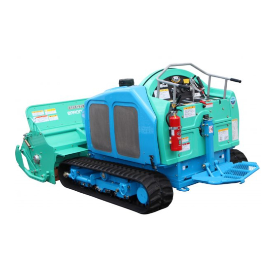
3.Part names 4.Features This energy-saving type large mowing machine with a diesel engine is manufactured for professional use especially for slope land operation. The mowing width is 154 or 170 cm, and the maximum output is 26.5 kW. The machine is ideal for mowing on river banks, skiing ground and major roads, as well as in other large areas. -
Page 9: Specifications
5.Specifications CAUTION For transportation of the machine, give attention to the width of the loading space. HMA1560 HMA1720 3,000mm(3,200mm Foot step) Total length 6. Inspection before use Dimensions Total width 1,717mm 1,910mm Inspect the machine according to "13. Maintenance schedule." 1,350mm Total height Mitsubishi Diesel S4L2-E231KM 1.758L (1,758 cm3) -
Page 10: Lubrication Of Friction Surface Of Each Part
6-4. Lubrication of friction surface of each part Operation lever and neutral positioning [8 places] Supply oil constantly to the inlet/outlet of the wire and the joint of each part to prevent rusting. Supply grease to the grease nipple every 50 hours. Crawler [26 places] Fulcrum of knife frame [2 places] Tension [3 places]... -
Page 11: Tightening Each Part
8-2. Engine start . operation method 7. Tightening each part Bolts are used for each part. After initial use of the machine, the bolts and nuts may get loose. Set the throttle lever in the high-speed range. Tighten loose bolts and nuts. Check the instruments. -
Page 12: Machine Operation
9. Machine operation 9-3.Traveling lever The traveling lever is at the center of the Mowing height adjustment 9-1. Machine operation CAUTION rear section of the machine. Push it Mowing height switch forward to move the machine forward, and Check that the operating condition of each part especially the safety of the side brake, High pull it back to your side to move the Forward... -
Page 13: Step (Simple Riding Unit)
9-6. Step (simple riding unit) hitch section by 11 mounting pin 32 and the nut with disc washer, and the knife can be removed easily. The step is kept horizontal at all times by the angle sensor, automatic level control box and Attach the mounting pin in the same direction as before. -
Page 14: Precautions As To Operation On A Steep Slope
11-2. Precautions as to operation on a steep slope 12-2. Prevention of damage due to high-pressure oil WARNING WARNING Be sure to observe the following matters when using the machine on a The high-pressure oil, when sprayed over the skin, will cause serious injury. Release the pressure before removing the high-pressure line, hose, and joints. -
Page 15: Maintenance Schedule
Maintenance schedule 14. Belt adjustment CAUTION 14-1. Knife Refer to the diesel engine operation manual for the method of handling the engine. Remove the knife shaft cover and adjust the tension of the belt put on the B3 V-pulley Inspection, adjustment, replenishment and cleaning 30150 and knife shaft V-pulley by using the tension pulley adjusting bolt. -
Page 16: Crawler
15-2. Installation . removal of crawler 15. Crawler When removing the crawler, loosen the M14 bolt (width across flats: 22) on the grease 15-1. Crawler tension cylinder, remove the grease, return the front roller to the original position, lift the crawler that is to be removed above the ground, and then remove the crawler. -
Page 17: Adjustment Of Neutral Position Of Piston Pump
16-1. Adjustment of neutral position of piston pump Loosen the mounting bolts of the neutral lever mounting bases for the pump on both sides to keep the bolts loose. Return the side brake lever to unlock the traveling lever. Start the engine, and move the neutral lever mounting bases for the pump by using a stick, etc. -
Page 18: Confirmation After Adjustment
16-3. Confirmation after adjustment Refer to the diesel engine operation manual for the method of handling the After the above-mentioned adjustment, confirm the following: engine. Stop the engine and move the respective levers to check for interference. Check that the machine is in the neutral position and will not move even if the engine is in the full-throttle state. -
Page 19: Attaching/Detaching The Mower Portion
19. Attaching/detaching the mower portion 19-2. Installation of the mower portion (The numbers in [ ] in the text correspond to the parts catalog Nos.) While engaging the hitch sections, slowly move the machine forward, and raise the CAUTION attachment mounting base to engage the hitch sections. Be sure to install and remove the mower portion in a flat horizontal place. -
Page 20: Wiring Diagram
21. Wiring diagram Glow timer Safety relay Blue(AV2) Green and red 4-pole ON-ON switch 2-pole ON-OFF-ON switch Starter switch connection (AV1.25) 2 11 8 9 12 6 3 10 7 Red(AV2) Black(AV2) Control timer (M5) Black(AV2) (M4) (M5) White and red(AV2) White(AV2) (M4) (M6) -
Page 21: Hydraulic Circuit
22. Hydraulic circuit Knife frame up/down (45-70-250 double-acting 2) KES-VU02T-00 a2 a1 MA6AD661 EDV1-02T-12V-00 VPF-06 HD-02413 KP1009 166/151 SP08 MAG-18P-150 PSV2-16A MAG-18P-150 (10 m) Hydraulic tank... -
Page 22: Parts Catalogue
CONTENTS Parts Catalogue 1. Operation lever 2. Neutral positioning 3. Crawler 4. Frame 5. Handle and brake 6. Knife frame 7. Tension 8. Knife 9. Engine and muffler 10. Fuel tank and air cleaner 11. Radiator 12. Electrical equipment 13. Electrical equipment box 14. - Page 23 Placing an order for parts The parts in this parts list are controlled by a computer. Be sure to specify the type of machine, catalog No., code No., and part name when placing orders for parts in order to avoid delivery of wrong parts. Example: Catalog No.
-
Page 24: Operation Lever
1. Operation lever... - Page 25 Catalog Remarks Catalog Remarks Code No. Part Name Code No. Part Name Location Location 1560 1560 1560 1720 1560 1720 1720 1720 1- 1 K 1 3 0 0 0 0 0 0 8 0 0 0 Handle grip 15.5 1-31 K 0 1 8 0 1 0 0 0 0 2 10 left-hand thread nut...
-
Page 26: Neutral Positioning
2. Neutral positioning... - Page 27 Catalog Remarks Catalog Remarks Code No. Part Name Code No. Part Name Location Location 1560 1560 1560 1720 1560 1720 1720 1720 2- 1 K 0 1 0 0 0 6 0 0 0 2 6 nut 2- 2 K 0 2 0 0 0 6 0 0 0 2 6S washer 2- 3 K 5 0 0 0 0 6 0 0 0 2...
-
Page 28: Crawler
3. Crawler 9. Engine and muffler... - Page 29 Catalog Remarks Catalog Remarks Code No. Part Name Code No. Part Name Location Location 1560 1560 1560 1720 1560 1720 1720 1720 3- 1 K 8 0 2 1 0 0 0 3 6 0 Front roller assy 3-37 K 0 1 6 0 0 0 0 0 4 2 20 special nut P1.5 B2,D3 etc.
-
Page 30: Frame
4. Frame (Optional part) - Page 31 Catalog Remarks Catalog Remarks Code No. Part Name Code No. Part Name Location Location 1560 1560 1560 1720 1560 1720 1720 1720 H M A 1 5 6 0 0 3 0 1 A V Frame 4-30 K 0 2 0 0 1 2 0 0 0 2 12S washer 4- 1 H M A 1 7 2 0 0 3 0 1 A V...
-
Page 32: Handle And Brake
5. Handle and brake... - Page 33 Catalog Remarks Catalog Remarks Code No. Part Name Code No. Part Name Location Location 1560 1560 1560 1720 1560 1720 1720 1720 5- 1 K 7 1 0 0 0 0 0 2 8 L Handle 5- 2 K 1 3 0 0 0 0 0 0 2 0 Handle grip 25.4 5- 3 K 6 2 1 2 0 0 1 2 5 2...
-
Page 34: Knife Frame
6. Knife frame (Optional part) (Optional part) - Page 35 Catalog Remarks Catalog Remarks Code No. Part Name Code No. Part Name Location Location 1560 1560 1560 1720 1560 1720 1720 1720 H M A 1 5 6 0 0 5 0 0 Z 0 Knife frame assy 6-26 6- 1 H M A 1 7 2 0 0 5 0 0 Z 0 Knife frame assy 6-27...
- Page 36 6. Knife frame (Optional part) (Optional part)
- Page 37 Catalog Remarks Catalog Remarks Code No. Part Name Code No. Part Name Location Location 1560 1560 1560 1720 1560 1720 1720 1720 6-49 K 5 0 7 3 2 1 0 2 6 2 3.2SPHC washer 1026 6-73 H M A 1 5 6 0 0 5 0 2 A V Attachment mounting base 6-50 6-74...
-
Page 38: Tension
7. Tension Upper cover To 9. Engine and muffler... - Page 39 Catalog Remarks Catalog Remarks Code No. Part Name Code No. Part Name Location Location 1560 1560 1560 1720 1560 1720 1720 1720 7- 1 K 8 0 3 0 0 0 0 0 2 0 Tension pulley assy 4155 7-40 K 6 0 8 3 0 0 0 0 2 2 Hexagon head tension pin 81 D3,E5...
-
Page 40: Knife
8. Knife... - Page 41 Catalog Remarks Catalog Remarks Code No. Part Name Code No. Part Name Location Location 1560 1560 1560 1720 1560 1720 1720 1720 K 8 1 1 0 1 5 5 0 0 R Knife shaft assy 1550 8-28 K 5 0 0 0 0 8 0 0 0 2 8 washer 8- 1 K 8 1 1 0 1 7 0 0 0 R...
-
Page 42: Engine And Muffler
9. Engine and muffler 3. Crawler From 7. Tension... - Page 43 Catalog Remarks Catalog Remarks Code No. Part Name Code No. Part Name Location Location 1560 1560 1560 1720 1560 1720 1720 1720 9- 1 K 0 0 0 0 0 6 0 1 5 2 6 bolt 15 A3,A4 etc. 9-31 H M 1 5 6 0 - 1 1 1 6 Z V Tool box...
- Page 44 9. Engine and muffler 3. Crawler From 7. Tension...
- Page 45 Catalog Remarks Catalog Remarks Code No. Part Name Code No. Part Name Location Location 1560 1560 1560 1720 1560 1720 1720 1720 9-61 K 0 6 6 3 0 0 5 0 0 0 Rhombic flange unit UFL005 9-62 K 0 4 0 1 0 2 5 0 0 1 Stop ring S25 9-63 K 7 3 5 5 0 0 0 1 2 V...
-
Page 46: Fuel Tank And Air Cleaner
10. Fuel tank and air cleaner Cover frame Rear frame Engine (Viewed from the opposite side) Knife frame Frame... - Page 47 Catalog Remarks Catalog Remarks Code No. Part Name Code No. Part Name Location Location 1560 1560 1560 1720 1560 1720 1720 1720 10- 1 K 0 0 0 0 0 6 0 1 2 2 6 bolt 12 10-36 10- 2 K 0 2 0 0 0 6 0 0 0 2 6S washer 10-37...
-
Page 48: Radiator
11. Radiator Engine Up Oil cooler Engine Low Rear frame... - Page 49 Catalog Remarks Catalog Remarks Code No. Part Name Code No. Part Name Location Location 1560 1560 1560 1720 1560 1720 1720 1720 11- 1 K 0 0 0 0 0 8 0 2 0 2 8 bolt 20 A3,A4 etc. 11-31 K 0 1 0 0 1 0 0 0 0 2 10 nut...
-
Page 50: Electrical Equipment
12. Electric equipment 15. Hydraulic tank Engine... - Page 51 Catalog Remarks Catalog Remarks Code No. Part Name Code No. Part Name Location Location 1560 1560 1560 1720 1560 1720 1720 1720 12- 1 K 3 6 6 2 0 0 0 0 3 0 Auto-return type switch ET115G 12-31 K 3 6 1 1 0 0 0 2 4 0 Battery earth cord 500 A4,D1...
-
Page 52: Electrical Equipment Box
13. Electric equipment box Rear frame... - Page 53 Catalog Remarks Catalog Remarks Code No. Part Name Code No. Part Name Location Location 1560 1560 1560 1720 1560 1720 1720 1720 13- 1 K 3 6 9 0 0 0 0 0 2 0 Horizontal controller box 13-31 K 3 6 2 0 0 0 0 0 5 0 Horizontal sensor wiring 13- 2 K 0 0 0 0 0 6 0 2 0 2...
-
Page 54: Hydraulic Pump
14. Hydraulic pump Hydraulic tank 15. Hydraulic tank 15. Hydraulic tank 15. Hydraulic tank 15. Hydraulic tank... - Page 55 Catalog Remarks Catalog Remarks Code No. Part Name Code No. Part Name Location Location 1560 1560 1560 1720 1560 1720 1720 1720 14- 1 K 0 0 0 0 0 8 0 2 0 2 8 bolt 20 A1,B3 14-29 K 5 2 2 0 0 0 0 4 0 2 Pump stop plate 14- 2...
- Page 56 14. Hydraulic pump Hydraulic tank 15. Hydraulic tank 15. Hydraulic tank 15. Hydraulic tank 15. Hydraulic tank...
- Page 57 Catalog Remarks Catalog Remarks Code No. Part Name Code No. Part Name Location Location 1560 1560 1560 1720 1560 1720 1720 1720 14-55 K 4 0 3 2 0 0 0 1 0 0 12 pipe cover 50 14-85 K 3 0 2 9 0 0 0 0 3 2 - Y Special bushing PF1/4PT1/4 14-56 K 5 2 7 6 0 0 0 2 2 2...
-
Page 58: Hydraulic Tank
15. Hydraulic tank Knife frame Shell Tellus ST46 Hydraulic pump Part of panel Electric equipment 14. Hydraulic pump 14. Hydraulic pump 14. Hydraulic Rear frame pump 14. Hydraulic pump... - Page 59 Catalog Remarks Catalog Remarks Code No. Part Name Code No. Part Name Location Location 1560 1560 1560 1720 1560 1720 1720 1720 15- 1 K 3 4 3 0 0 0 0 0 2 0 Oil cooler 15-31 15- 2 K 3 1 0 1 4 3 1 2 0 0 WP70-12 hose 3-1200 15-32...
- Page 60 15. Hydraulic tank Knife frame Shell Tellus ST46 Hydraulic pump Part of panel Electric equipment 14. Hydraulic pump 14. Hydraulic pump 14. Hydraulic Rear frame pump 14. Hydraulic pump...
- Page 61 Catalog Remarks Catalog Remarks Code No. Part Name Code No. Part Name Location Location 1560 1560 1560 1720 1560 1720 1720 1720 15-61 H M A 1 5 6 0 1 0 0 1 A D - Y Hydraulic tank 15-91 K 3 1 0 3 2 1 0 7 0 0 WP140-6 hose 1-700...
-
Page 62: Upper Cover
16. Upper cover Lower cover 7. Tension... - Page 63 Catalog Remarks Catalog Remarks Code No. Part Name Code No. Part Name Location Location 1560 1560 1560 1720 1560 1720 1720 1720 16- 1 H M A 1 5 6 0 1 1 0 3 Z 0 Operation panel COMP 16-44 16- 2 K 3 1 9 7 0 0 3 2 0 0...
-
Page 64: Lower Cover
17. Lower cover 16. Upper cover View A Part of cover... - Page 65 Catalog Remarks Catalog Remarks Code No. Part Name Code No. Part Name Location Location 1560 1560 1560 1720 1560 1720 1720 1720 17- 1 K 0 0 0 0 0 6 0 1 5 2 6 bolt 15 B1,C2 etc. 17-31 K 5 1 3 0 0 0 0 2 1 G Rear knife shaft cover...
-
Page 66: Tools And Spares
18. Tools and spares (Option parts) (Option parts) - Page 67 Catalog Remarks Catalog Remarks Code No. Part Name Code No. Part Name Location Location 1560 1560 1560 1720 1560 1720 1720 1720 18- 1 K 4 8 7 0 0 0 0 0 2 0 Engine oil funnel 18 18- 2 K 2 5 2 0 0 0 0 0 4 B Hammer knife 6110 18- 3...
Need help?
Do you have a question about the Baroness HMA1560 and is the answer not in the manual?
Questions and answers