Bunn Single SH Operating And Service Manual
Hide thumbs
Also See for Single SH:
- Installation and operating manual (48 pages) ,
- Operating & service manual (44 pages) ,
- Illustrated parts catalog (35 pages)
Table of Contents
Advertisement
Quick Links
BUNN
OPERATING & SERVICE MANUAL
28230.0000F 3/01 ©1997 Bunn-O-Matic Corporation
All manuals and user guides at all-guides.com
E R
N
N T
IO
C A
U T
D E
C A
R D
C A
D IS
!
IF :
E D
D
P TY
C K
H E
R A
A TC
Y
E M
A M
E
. C
D R
E N
IC
C R
E D
W H
FL
C TR
. S
O IL
H
. B
D
H IG
E LE
E A
TE
O N
D
. H
D
S E
S E
P O
. U
E X
N TS
R
M E
Y
. O
U R
E LE
IN J
T S
IO
N
E N
K S
AT
OR
N T
R IS
RP
C O
L Y
IC
CO
O T
AT
E L
M P
-M
N N
E H
C O
NN
-O
F U
A R
BU
T O
85
R E
19
IL U
F A
: 65
8
PN
BUNN-O-MATIC CORPORATION
POST OFFICE BOX 3227
SPRINGFIELD, ILLINOIS 62708-3227
PHONE: (217) 529-6601 FAX: (217) 529-6644
®
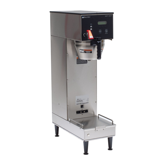
SINGLE
1.50 & 1.75 GALLON
E R
A T
T W
H O
N
IO
U T
C A
!
™
SH
www.bunnomatic.com
Advertisement
Table of Contents

Subscribe to Our Youtube Channel
Related Manuals for Bunn Single SH


Summary of Contents for Bunn Single SH
- Page 1 H IG E LE N TS E LE IN J R IS IL U : 65 OPERATING & SERVICE MANUAL BUNN-O-MATIC CORPORATION POST OFFICE BOX 3227 SPRINGFIELD, ILLINOIS 62708-3227 PHONE: (217) 529-6601 FAX: (217) 529-6644 www.bunnomatic.com 28230.0000F 3/01 ©1997 Bunn-O-Matic Corporation...
- Page 2 SPECIFIED HEREIN, TO REPAIR OR, AT BUNN’S SOLE OPTION, REPLACEMENT OR REFUND. In no event shall Bunn be liable for any other damage or loss, including, but not limited to, lost profits, lost sales, loss of use of equipment, claims of Buyer’s customers, cost of capital, cost of down time, cost of substitute equipment, facilities or services, or any other special, incidental or consequential damages.
- Page 3 All manuals and user guides at all-guides.com USER NOTICES The notices on this brewer should be kept in good condition. Replace unreadable or damaged labels. 00658.0000 00831.0000 WARNING HOT WATER 20201.5600 00656.0000 ELECTRICAL REQUIREMENTS CAUTION - The brewer must be disconnected from the power source until specified in Initial Set-Up. L2 RED WHITE 120 V.A.C.
- Page 4 " water supply line. A tight coil of copper tubing in the water line will facilitate moving the brewer to clean the countertop. Bunn-O-Matic does not recommend the use of a saddle valve to install the brewer. The size and shape of the hole made in the supply line by this type of device may restrict water flow.
- Page 5 All manuals and user guides at all-guides.com INITIAL SET-UP CAUTION – The brewer must be disconnected from the power source throughout the initial set-up, except when specified in the instructions. 1. Remove the front panel beneath the sprayhead and rotate the control thermostat knob fully counterclockwise to the “OFF”...
- Page 6 All manuals and user guides at all-guides.com ADJUSTING BREW VOLUMES CAUTION - Disconnect the power source from the brewer prior to the removal of any panel for the replacement or adjustment of any component. NOTE: Prior to setting or modifying batch sizes, check that the brewer is connected to water supply, the tank is properly filled, and a funnel and server are in place.
- Page 7 NOTE: The On/Off switch must be in the lighted upper position to initiate and complete a brew cycle. COFFEE BREWING 1. Select the desired batch size. 2. Insert a BUNN ® filter into the funnel. 3. Pour the proper amount of fresh coffee into the filter and level the bed of grounds by gently shaking.
- Page 8 All manuals and user guides at all-guides.com TROUBLESHOOTING A troubleshooting guide is provided to suggest probable causes and remedies for the most likely problems encountered. If the problem remains after exhausting the troubleshooting steps, contact the Bunn-O-Matic Technical Service Department. •...
- Page 9 All manuals and user guides at all-guides.com TROUBLESHOOTING (cont.) Problem Probable Cause Remedy Brew cycle will not start (cont.) 2. Water strainer/flow control (.500 (A) Direction of flow arrow must be GPM) pointing towards brewer. (B) Remove the strainer/flow con- trol and check for obstructions.
- Page 10 All manuals and user guides at all-guides.com TROUBLESHOOTING (cont.) Problem Probable Cause Remedy Beverage level will not adjust (Selec- 1. Brew selector switch Refer to Service - Selector switch for tor switch in any position) testing procedures. See page 16 Water flows into tank continuously 1.
- Page 11 Refer to Adjustments on page 4 step Water overflows filter. 1. Bypass valve #7. For test procedures see page 15 ® 2. Type of paper filters BUNN paper filters should be used for proper extraction. 3. No sprayhead Check sprayhead Beverage overflows server.
- Page 12 B.O.M. Sprayhead #01082.0002 should be used to properly wet the bed of ground coffee in the funnel. ® 4. Funnel loading The BUNN paper filter should be centered in the funnel and the bed of ground coffee leveled by gentle shak- ing.
- Page 13 All manuals and user guides at all-guides.com TROUBLESHOOTING (cont.) Probable Cause Remedy Problem 1. Circuit breaker A) Check and reset if necessary Server will not heat B) Refer to Service - Circuit breaker for test procedures. See page 18 2. Receptacle contact Clean or replace.
-
Page 14: Table Of Contents
All manuals and user guides at all-guides.com COMPONENT ACCESS SERVICE WARNING - Disconnect the brewer from the power This section provides procedures for testing source before the removal of any panel or the replace- and replacing various major components used in this ment of any component. -
Page 15: Bypass Valve
All manuals and user guides at all-guides.com SERVICE (cont.) a.) 120 volts ac for two wire 120 volt models, 208 volts ac for three wire 120/208 volt models and BYPASS VALVE 240 volts ac for three wire 120/240 volt models. b.) 200 to 240 volts ac for two wire 200 or 240 volt 22978.0000 models. -
Page 16: Brewer Selector Switch
All manuals and user guides at all-guides.com SERVICE (cont.) BREW SELECTOR SWITCH Grinder Interface: 7. Disconnect the pink, gray and tan wires on the selector switch from the pink, gray and tan wires on the interface socket. 8. Check for continuity across the pink wire and tan wire on the selector switch when the switch is in the 1/2 gallon position. - Page 17 All manuals and user guides at all-guides.com SERVICE (cont.) BREW SELECTOR SWITCH (cont.) Removal and Replacement: 1. Disconnect the connector on the selector switch harness from the brewer timer circuit board. 2. Disconnect wires from the selector switch, inter- face socket, dispense valve and bypass valve. 3.
-
Page 18: Circuit Breaker
All manuals and user guides at all-guides.com SERVICE (cont.) CIRCUIT BREAKERS Removal and Replacement: 1. Remove the wires from the circuit breaker. 2. Compress the clips on the back side of the server platform and gently push the circuit breaker through the opening in the server platform. -
Page 19: Limit Thermostat
All manuals and user guides at all-guides.com SERVICE (cont.) LIMIT THERMOSTAT Removal and Replacement: 1. Remove all wires from the limit thermostat termi- nals. 22978.0000 2. Carefully remove the two #8-32 nuts securing the limit thermostat to tank lid and remove limit ther- mostat. -
Page 20: Contactor Assembly
All manuals and user guides at all-guides.com SERVICE (cont.) wire 120/208 volt models and three wire 120/240 CONTACTOR ASSEMBLY volt models. b.) 200 to 240 volts ac for two wire 200, 230 or 240 volt models. 22978.0000 5. Disconnect the brewer from the power source. If voltage is present as described, proceed to #6. - Page 21 All manuals and user guides at all-guides.com SERVICE (cont.) CONTACTOR ASSEMBLY If continuity is present as described, the contactor is operating properly. If continuity is not present as described, replace the contactor. Removal and Replacement: 1. Remove all wires from the contactor. 2.
-
Page 22: Control Thermostat
All manuals and user guides at all-guides.com SERVICE (cont.) CONTROL THERMOSTAT If voltage is present as described, reconnect the wire and proceed to #5. If voltage is not present as described, refer to the 22978.0000 wiring diagrams and check the brewer wiring harness. 5. - Page 23 All manuals and user guides at all-guides.com SERVICE (cont.) 7. Using a #8-32 slotted head screw fasten the con- CONTROL THERMOSTAT (cont.) trol thermostat to the component bracket. 8. Refer to FIG. 13 when reconnecting the wires. Removal and Replacement: 9.
-
Page 24: Dispense Valve
All manuals and user guides at all-guides.com SERVICE (cont.) DISPENSE VALVE 4. Check for continuity across the dispense valve coil terminals. 22978.0000 If continuity is present as described, reconnect the wires to the dispense valve and proceed to #5. If continuity is not present as described, replace the dispense valve. -
Page 25: Overflow Protection Switch
All manuals and user guides at all-guides.com Removal and Replacement: SERVICE (cont.) 1. Disconnect the red leads from the overflow pro- OVERFLOW PROTECTION SWITCH tection switch from the black wire from the termi- nal block and the blue wire from the thermostat. 2. -
Page 26: Level Control Board And Level Probe
All manuals and user guides at all-guides.com SERVICE (cont.) 6. Carefully connect a piece of insulated jumper wire LEVEL CONTROL BOARD AND LEVEL PROBE to terminal 4. Keep the other end of this wire away from any metal surface of the brewer. 7. - Page 27 All manuals and user guides at all-guides.com SERVICE (cont.) Removal and Replacement: LEVEL CONTROL BOARD AND LEVEL PROBE 1. Remove all wires from the level control board. 15. Move the probe's flat end to the brewer housing. 2. Remove two #8-32 slotted head screws and The indication must be 0.
-
Page 28: On/Off Switch
All manuals and user guides at all-guides.com SERVICE (cont.) 6. Check for continuity across the center and lower left terminal with switch in the "ON" position. ON/OFF SWITCH Continuity must not be present when switch is in the "OFF" position. If continuity is present as described, reconnect the black wire to the center terminal and the white/violet wire on the switch to the lower left terminal. -
Page 29: Receptacle (Spring Contacts)
All manuals and user guides at all-guides.com SERVICE (cont.) RECEPTACLE ASSEMBLY (SPRING CONTACT) Removal and Replacement: 1. Disconnect the brewer from the power source. D EL . HE R EX R IS IL U 2. Disconnect the wires from the receptacle assem- : 65 bly. -
Page 30: Rectifier
All manuals and user guides at all-guides.com SERVICE (cont.) Removal and Replacement: RECTIFIER 1 Disconnect the wires from the rectifier. 2. Remove the #6-32 truss head screw securing the rectifier to the brew base plate. 3. Remove the rectifier and discard. 4. -
Page 31: Relay (Server Power)
All manuals and user guides at all-guides.com SERVICE (cont.) If continuity is not present as described, replace the relay. RELAY (SERVER POWER)(Prior to S.N. SNG0014000) 5. Disconnect the white/yellow from terminal 6 and white/orange wire from terminal 9 on the relay. 6. -
Page 32: Solenoid Valve
All manuals and user guides at all-guides.com SERVICE (cont.) If continuity is present as described, reconnect the SOLENOID VALVE white and violet wires on 120, 120/208 and 120/240 volt brewers, red and violet wires on 200, 230 or 240 22978.0000 volt brewers. -
Page 33: Start Switch (Brew)
All manuals and user guides at all-guides.com SERVICE (cont.) WITH RELAY (Prior to S.N. SNG0014000) START SWITCH GRN to Server Power Relay "A" WHI/VIO to ON/OFF Switch and Brew Timer TL1 WITHOUT RELAY(After S.N. SNG0014000) WHI/YEL to Timer #5 T IO BLK To SH P1357 FIG. -
Page 34: Tank Heater
All manuals and user guides at all-guides.com SERVICE (cont.) NOTE - If the tank heater remains unable to heat, TANK HEATER remove and inspect the heater for cracks in the sheath. Removal and Replacement: 22978.0000 Remove wires from tank heater. Remove the four #8-32 nuts securing tank heat to tank lid. -
Page 35: Transformer
All manuals and user guides at all-guides.com SERVICE (cont.) TRANSFORMER 6. With a voltmeter check the voltage across the blue/ black wires. Connect the brewer to the power source. The indication must be 24 volts ac. If voltage is present as described the transformer is operating properly. -
Page 36: Timer (Early Models)
All manuals and user guides at all-guides.com SERVICE (cont.) TIMER (Early Models) If voltage is present as described, reconnect white/ orange wire to TL3, white/green wire to TL4, white/ yellow wire to TL5 and proceed to #5. 22978.0000 If voltage is not present as described, refer to the wiring diagrams and check the brewer wiring harness. - Page 37 All manuals and user guides at all-guides.com SERVICE (cont.) WITH RELAY (Prior to S.N. SNG0014000) TIMER (cont.) Removal and Replacement: 1. Remove all wires from the timer. 2. Remove the four #6-32 slotted head screws hold- ing circuit board and dial plate on to the compo- nent mounting bracket.
-
Page 38: Digital Brew Timer (Late Models)
All manuals and user guides at all-guides.com SERVICE (cont.) DIGITAL TIMER (Late Models) 6. With a voltmeter, check the voltage across termi- nals TL1 and TL4 when the "ON/OFF" switch is in the "ON" position. Connect the brewer to the power source. - Page 39 All manuals and user guides at all-guides.com SERVICE (cont.) DIGITAL TIMER (Late Models)(cont.) Timer Setting: NOTE: Check that the brewer is connected to water supply, the tank is properly filled, and a funnel and server are in place, prior to setting or modifying volumes.
-
Page 40: Wiring Diagrams
CIRCUIT RECTIFIER BREAKER 120 VOLTS AC 2 WIRE 120/208 VOLTS AC OR BLU/BLK – 120/240 VOLTS AC 3 WIRE 24VDC TRANSFORMER SINGLE PHASE – 28170.0000C 9/98 © 1997 BUNN-O-MATIC CORPORATION Front view of Brewer Server Connector Page 40 28230 092200... - Page 41 INTERFACE SWITCH CONNECTOR WHI/VIO BLU/BLK BLU/BLK – CIRCUIT RECTIFIER BREAKER RESETTABLE FUSE BLU/BLK 230 VOLTS AC 2 WIRE – 24VDC SINGLE PHASE TRANSFORMER – 28170.0001C 11/98 © 1998 BUNN-O-MATIC CORPORATION Front view of Brewer Server Connector Page 41 28230 092200...
- Page 42 CIRCUIT RECTIFIER BREAKER 120 VOLTS AC 2 WIRE 120/208 VOLTS AC OR BLU/BLK – 120/240 VOLTS AC 3 WIRE 24VDC TRANSFORMER SINGLE PHASE – 28170.0003A 9/99 © 1999 BUNN-O-MATIC CORPORATION Front view of Brewer Server Connector Page 42 28230 092200...
- Page 43 SERVER DETECT BOARD BLU/BLK BLU/BLK – CIRCUIT FAUCET TUBE HEATER RECTIFIER BREAKER BLU/BLK – 24VDC 208/240 VOLTS AC 2 WIRE TRANSFORMER – SINGLE PHASE Front view of Brewer Server Connector 28170.0004B 11/99 © 1999 BUNN-O-MATIC CORPORATION Page 43 28230 092200...
- Page 44 All manuals and user guides at all-guides.com SINGLE SH BREWER W/DIGITAL BREWER CONTROL SCHEMATIC WIRING DIAGRAM WHI/RED J1-1 WHI/RED ON/OFF SW WHI/RED TRIAC REFILL WHI/VIO LIMIT THERMOSTAT TANK HEATER 120V.A.C. 208 0R 240V.A.C. 120V.A.C. BREW WHI/BLU OPTIONAL BYPASS J1-24 WHI/VIO...
Need help?
Do you have a question about the Single SH and is the answer not in the manual?
Questions and answers