Miele KM 7564 FR Operating And Installation Instructions
Hide thumbs
Also See for KM 7564 FR:
- Operating and installation instructions (88 pages) ,
- Installation manual (26 pages) ,
- Operating and installation instructions (96 pages)

Related Manuals for Miele KM 7564 FR


Summary of Contents for Miele KM 7564 FR
- Page 1 Operating and installation instructions Induction hobs To avoid the risk of accidents or damage to the appliance it is essen- tial to read these instructions before it is installed and used for the first time. en-GB M.-Nr. 11 184 730...
-
Page 3: Table Of Contents
Cooking zones..................... 24 Before using for the first time ................29 Cleaning the hob for the first time............... 29 Switching on the hob for the first time ..............29 Miele@home ......................30 Con@ctivity......................33 How it works ...................... 35 Noises........................35 Power management .................... - Page 4 Contents Using both timer functions at the same time ............51 Additional functions ..................52 Stop & Go......................52 Recall........................52 Wipe protection ....................53 Demonstration mode................... 53 Displaying hob data..................... 53 Safety features....................54 System lock/safety lock ..................54 Safety switch-off ....................55 Overheating protection..................
- Page 5 Contents Installation dimensions – Surface-mounted ............76 KM 7564 FR ....................76 KM 7564 FL ....................77 KM 7574 FR ....................78 KM 7574 FL ....................79 KM 7575 FR ....................80 KM 7575 FL ....................81 KM 7594 FR ....................82 KM 7594 FL ....................83 KM 7684 FL ....................84 Surface-mounted installation ................85 Installation dimensions – Flush-fit ............... 86 KM 7564 FL ....................
-
Page 6: Warning And Safety Instructions
Miele cannot be held liable for injury or damage caused by non- compliance with these instructions. Keep these instructions in a safe place and pass them on to any... - Page 7 Warning and Safety instructions Correct application This hob is intended for domestic use and use in other similar en- vironments. This hob is not intended for outdoor use. It is intended for domestic use only to cook food and keep it warm.
- Page 8 Warning and Safety instructions Safety with children Children under 8 years of age must be kept away from the hob unless they are constantly supervised. Children over 8 years of age may use the hob without supervision if its operation has been clearly explained to them and they are able to use it safely.
- Page 9 Unauthorised installation, maintenance and repairs can cause considerable danger for the user. Installation, maintenance and re- pairs must only be carried out by a Miele authorised technician. Damage to the hob can compromise your safety. Check the hob for visible signs of damage.
- Page 10 Miele authorised service technician. Otherwise the war- ranty is invalidated. Miele can only guarantee the safety of the appliance when genu- ine original Miele replacement parts are used. Faulty components must only be replaced by Miele spare parts.
- Page 11 Warning and Safety instructions If the hob is installed behind a cabinet door, do not close the door while the hob is in use. Heat and moisture can build up behind the closed door. This can result in damage to the hob, the housing unit and the floor.
- Page 12 Warning and Safety instructions Correct use The hob gets hot when in use and remains hot for a while after be- ing switched off. There is a danger of burning until the residual heat indicators go out. Oil and fat can overheat and catch fire. Do not leave the hob unat- tended when cooking with oil and fat.
- Page 13 Warning and Safety instructions You could burn yourself on the hot hob. Protect your hands with heat-resistant pot holders or gloves when handling hot pots and pans. Do not let them get wet or damp, as this causes heat to trans- fer through the material more quickly with the risk of scalding or burning yourself.
- Page 14 Warning and Safety instructions Because induction heating works so quickly, the base of the pan could, under certain circumstances, heat up to the temperature at which oil or fat self-ignites within a very short time. Never leave the hob unattended during use! ...
- Page 15 (see relev- ant section). Miele will guarantee to supply functional spare parts for a min- imum of 10 years and up to 15 years following the discontinuation of your hob.
-
Page 16: Caring For The Environment
/ recycling centre for electrical and electronic ap- pliances, or contact your dealer or Miele for advice. You are also respons- ible for deleting any personal data that may be stored on the appliance being disposed of. Please ensure that your old appliance poses no risk to children while being stored prior to disposal. -
Page 17: Guide To The Appliance
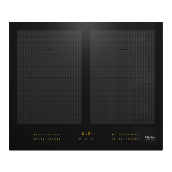
Guide to the appliance KM 7564 FR, KM 7564 FL a PowerFlex cooking zone with TwinBooster b PowerFlex cooking zone with TwinBooster can be combined with PowerFlex cooking zone to form PowerFlex cooking area c PowerFlex cooking zone with TwinBooster can be combined with PowerFlex cooking zone to form PowerFlex cooking area d PowerFlex cooking zone with TwinBooster e Controls and indicators... -
Page 18: Km 7574 Fr, Km 7574 Fl
Guide to the appliance KM 7574 FR, KM 7574 FL a Cooking zone with TwinBooster b Cooking zone with TwinBooster c PowerFlex cooking zone with TwinBooster can be combined with PowerFlex cooking zone to form PowerFlex cooking area d PowerFlex cooking zone with TwinBooster e Controls and indicators... -
Page 19: Km 7575 Fr, Km 7575 Fl
Guide to the appliance KM 7575 FR, KM 7575 FL a PowerFlex cooking zone with TwinBooster b PowerFlex cooking zone with TwinBooster can be combined with PowerFlex cooking zone to form PowerFlex cooking area c PowerFlex cooking zone with TwinBooster can be combined with PowerFlex cooking zone to form PowerFlex cooking area d PowerFlex cooking zone with TwinBooster can be combined with PowerFlex cooking zone ... -
Page 20: Km 7594 Fr, Km 7594 Fl
Guide to the appliance KM 7594 FR, KM 7594 FL a PowerFlex cooking zone with TwinBooster b PowerFlex cooking zone with TwinBooster can be combined with PowerFlex cooking zone to form PowerFlex cooking area c Cooking zone with TwinBooster d PowerFlex cooking zone with TwinBooster can be combined with PowerFlex cooking zone ... - Page 21 Guide to the appliance KM 7684 FL a PowerFlex cooking zone with TwinBooster b PowerFlex cooking zone with TwinBooster can be combined with PowerFlex cooking zone to form PowerFlex cooking area c PowerFlex cooking zone with TwinBooster d PowerFlex cooking zone with TwinBooster can be combined with PowerFlex cooking zone ...
-
Page 22: Controls And Display
Guide to the appliance Controls and display Sensor controls a Hob On/Off b Stop & Go To stop/start a cooking process in progress c Wipe protection To lock the sensor controls d PowerFlex cooking zones For manual connection/disconnection of PowerFlex cooking zones e Keeping warm To activate/deactivate the Keeping warm function f Numerical display... - Page 23 Guide to the appliance Displays/indicator lights i Cooking zone allocation auto switch off Auto switch off for the cooking zone is activated j Residual heat k Booster function Booster function is activated l Timer display : to Time : System lock/safety lock is activated ...
-
Page 24: Cooking Zones
Guide to the appliance Cooking zones KM 7564 FR, KM 7564 FL Cooking Size in cm Max. rating Linked cooking zone in watts for 230 V zone Ø 15–23 19 x 23 Normal 2100 TwinBooster, level 1 3000 TwinBooster, level 2 3650 15–23 19 x 23 Normal 2100 ... - Page 25 Guide to the appliance KM 7574 FR, KM 7574 FL Cooking Size in cm Max. rating Linked cooking zone in watts for 230 V zone Ø 16–22 – Normal 2300 TwinBooster, level 1 3000 TwinBooster, level 2 3650 10–16 – Normal 1400 TwinBooster, level 1...
- Page 26 Guide to the appliance KM 7575 FR, KM 7575 FL Cooking Size in cm Max. rating Linked cooking zone in watts for 230 V zone Ø 15–23 19 x 23 Normal 2100 TwinBooster, level 1 3000 TwinBooster, level 2 3650 15–23 19 x 23 Normal 2100 TwinBooster, level 1 3000...
- Page 27 Guide to the appliance KM 7594 FR, KM 7594 FL Cooking Size in cm Max. rating Linked cooking zone in watts for 230 V zone Ø 15–23 19 x 23 Normal 2100 TwinBooster, level 1 3000 TwinBooster, level 2 3650 15–23 19 x 23 Normal 2100 TwinBooster, level 1 3000...
- Page 28 Guide to the appliance KM 7684 FL Cooking Size in cm Max. rating Linked cooking zone in watts for 230 V zone Ø 15–23 19 x 23 Normal 2100 TwinBooster, level 1 3000 TwinBooster, level 2 3650 15–23 19 x 23 Normal 2100 TwinBooster, level 1 3000...
-
Page 29: Before Using For The First Time
Before using for the first time Please stick the extra data plate for Switching on the hob for the the appliance supplied with this doc- first time umentation in the space provided in The metal components have a protect- the “After sales service”... -
Page 30: Miele@Home
Before using for the first time Miele@home availability Miele@home The ability to use the Miele app de- Prerequisite: home WiFi network pends on the availability of the Miele@home service in your country. Your hob is equipped with an integrated WiFi module. The hob can be connec- The Miele@home service is not avail- ted to your home WiFi network. - Page 31 Connecting via WPS Prerequisite: you must have a WPS Connecting via the app (WiFi protected setup) compatible The Miele app can be used to connect router. to your network. Switch the hob on. Install the Miele app on your mobile device.
- Page 32 Before using for the first time Cancelling the process Touch any sensor control. Resetting settings Resetting is not required when repla- cing the router. Switch the hob on. Touch the 0 sensor control on any of the numerical displays. ...
-
Page 33: Con@Ctivity
Before using for the first time Setting up Con@ctivity Con@ctivity Con@ctivity is the direct communication Con@ctivity via the home WiFi net- system between your hob and a Miele work (Con@ctivity 3.0) cooker hood. Con@ctivity enables the Requirements: cooker hood to operate automatically... - Page 34 Before using for the first time Con@ctivity via a direct WiFi connec- Cancelling the process tion (Con@ctivity 3.0) Touch any sensor control. You can find the necessary informa- Resetting settings tion on connecting the cooker hood in the associated operating and installa- Resetting is not required when repla- tion instructions.
-
Page 35: How It Works
How it works An induction coil is located under each Noises induction cooking zone. The coil cre- When using an induction hob, the fol- ates a magnetic field that reacts directly lowing noises can occur in the pan, de- with the base of the pan and heats it pending on what it is made of and how up. -
Page 36: Power Management
How it works If the new cooking zone requires more Power management power than the first cooking zone can The hob has a maximum total permitted provide, this may result in the following power consumption which cannot be consequences for the first cooking exceeded for safety reasons. -
Page 37: Pans
Pans Suitable pans No pan/unsuitable pan display - stainless steel pans with a magnetic The set power level flashes in the nu- base merical keybank for the cooking zone - enamelled steel pans - if the zone has been switched on without a pan in place, or if the pan is - cast iron pans unsuitable (non-magnetic base) - Page 38 Pans - Please note that the maximum dia- Tips meter quoted by manufacturers often - To make optimum use of the cooking refers to the diameter of the top rim zones, choose cookware with a suit- of the pots and pans. The diameter of able base diameter (see “Overview –...
-
Page 39: Tips On Saving Energy
Tips on saving energy - Use a lid whenever possible to min- imise heat loss. - Select a smaller pan when cooking small quantities. A smaller pan uses less energy than a larger pan with very little in it. - Cook with as little water as possible. - Once food has come to the boil or the oil in the pan is hot enough for frying, reduce the heat to a lower set-... -
Page 40: Setting Ranges
Setting ranges The hob is programmed with 9 power levels at the factory. If you wish to fine-tune a setting, you can extend the power level range to 17 power levels (see “Program- ming”). Setting range Factory set- Extended set- ting ting (9 power (17 power levels) -
Page 41: Operation
Operation Using the appliance Malfunction due to dirty and/or covered sensor controls. This ceramic hob is equipped with elec- If the sensor controls are dirty or tronic sensor controls which react to covered this could cause them to fail finger contact. -
Page 42: Switching On The Hob
Operation Switching off a cooking zone Risk of fire with overheated food. Unattended food can overheat and To switch off a cooking zone, touch catch alight. the 0 sensor for that cooking zone. Do not leave the hob unattended ... -
Page 43: Power Level Setting - Extended Setting Range
Operation Power level setting - Extended setting range Touch the numerical keybank in between two number sensors. The numbers to the left and right of the interim level light up brighter than the others. Example: If you have set power level 7. the num- bers 7 and 8 will be brighter than the other numbers. -
Page 44: Powerflex Cooking Area
Operation PowerFlex cooking area (pot) PowerFlex cooking area The PowerFlex cooking zones combine automatically to form a PowerFlex cooking area when you place suffi- ciently large items of cookware on them (see “Guide to the appliance – Hob”). Settings for the linked cooking area are controlled by the numerical display of the front or left PowerFlex cooking zone (depending on model). -
Page 45: Auto Heat-Up
Operation Auto heat-up Continued cook- Heat-up time ing setting* [min : sec] When Auto heat-up has been activated, the cooking zone switches on automat- Approx. 0:15 ically at the highest setting and then Approx. 0:15 switches to the continued cooking set- ting which you have previously selec- Approx. -
Page 46: Booster Function
Operation If the Booster function is switched on Booster function when: The cooking zones are equipped with a - No power level has been selected, TwinBooster. the cooking zone will revert automat- When the Booster function is activated, ically to level 9 at the end of the the power is boosted so that large Booster time or if the Booster func- quantities can be heated up quickly,... - Page 47 Operation Activating the TwinBooster Level 1 Place the cookware on the cooking zone you want to use. Select a power level if necessary. Touch the B sensor control. The indicator light for TwinBooster level 1 lights up. Level 2 ...
-
Page 48: Keeping Warm
Operation Activating/deactivating the keeping Keeping warm warm function This function is for keeping food warm Touch the sensor for the cooking which has just been cooked and is still zone you wish to use. hot. It is not for reheating food that has gone cold. -
Page 49: Timer
Timer Minute minder The hob has to be switched on if you want to use the timer. The minute minder is set using the nu- merical display for the left or front left The timer can be used for the following cooking zone (depending on model). -
Page 50: Auto Switch Off
Timer the sensor control repeatedly until Auto switch off the indicator light for the desired You can set a time after which a cook- cooking zone pulsates. ing zone will switch off automatically. This function can be used for all cook- Changing the switch-off time ing zones at the same time. -
Page 51: Using Both Timer Functions At The Same Time
Timer Using both timer functions at the same time If you use both functions simultan- eously, the shortest time is always dis- played. The sensor control (minute minder) or the sensor control (auto switch off) of the cooking zone with the shortest time pulsates. -
Page 52: Additional Functions
Additional functions Stop & Go Recall When Stop & Go is activated, the power If the hob is switched off in error during of all cooking zones in use is reduced to operation, this function can be used to power level 1. reset all settings. For this to work, the The cooking zone power levels and the hob must be switched on again within timer settings cannot be altered;... -
Page 53: Wipe Protection
Additional functions Wipe protection Displaying hob data The model number and software ver- The hob sensors can be locked for sion of the hob can be displayed. There 20 s in order, for example, to remove must not be any pots or pans on the soiling. -
Page 54: Safety Features
Safety features Activating the system lock System lock/safety lock Touch the sensor for 6 seconds. Your hob is equipped with a system lock and a safety lock to prevent the The seconds can be seen counting hob and the cooking zones being down in the timer display. -
Page 55: Safety Switch-Off
Safety features Safety switch-off Power level* Maximum operating time [h:min] Sensor controls are covered Safety setting Your hob will turn off automatically if one or several of the sensors remain 10:00 8:00 5:00 covered for longer than 10 seconds, for example, by finger contact, food boiling 10:00 7:00... -
Page 56: Overheating Protection
Safety features The overheating protection may be ac- Overheating protection tivated under the following circum- All the induction coils and heat sinks for stances: the electronic module are fitted with an - The cookware being heated is empty. overheating protection mechanism. Be- fore the induction coils or heat sinks get - Fat or oil is being heated on a high too hot, the overheating protection... -
Page 57: Programming
Programming You can adapt the programming of the To save the settings hob to your personal needs. Several While the programme is showing in settings can be altered in succession. the display (e. g. :) touch the sensor until the indicators go out. After accessing programming mode, the symbol appears and ... - Page 58 C:02 Active and configured (cannot be selec- ted; displays whether connection was successful) C:03 Connection possible via WPS push but- C:04 C:00 WiFi reset to default ( C:05 Direct WiFi connection of hob and cooker hood without Miele app (Con@ctivity 3.0)
- Page 59 Programming Settings Programme Code P:12 Sensor controls reaction speed C:00 Slow Normal C:01 C:02 Fast Permanent pan recognition Permanent pan recognition off P:15 C:00 C:01 Permanent pan recognition on Keeping warm temperature 50 °C P:25 C:00 C:01 55 °C 60 °C C:02 C:03 65 °C 70 °C C:04...
-
Page 60: Note For Test Institutes
Note for test institutes Test food acc. to EN 60350-2 9 power levels are programmed at the factory. For testing in accordance with the above standard, programme the hob to the ex- tended power level setting. Power level Test food Pan base (mm) Pre-heat Cooking Heating oil up... -
Page 61: Cleaning And Care
Cleaning and care Clean the hob after every use. Risk of burning due to hot cook- ing zones. Dry the hob thoroughly after cleaning with water to avoid limescale residue. The cooking zones will be hot after use. - Page 62 Then clean the ceramic glass surface able for use on glass. with the Miele ceramic and stainless steel hob cleaner (see “optional ac- Afterwards, clean the ceramic surface cessories”) or with a proprietary...
-
Page 63: Problem Solving Guide
Problem solving guide Many malfunctions and faults that can occur in daily operation can be easily remedied. Time and money will be saved because a service call will not be needed. The following guide may help you to find the reason for a malfunction or a fault, and to correct it. - Page 64 Problem solving guide Problem Cause and remedy will flash alternately The fan is blocked or defective. with , or in Make sure it has not been blocked by an object. the timer display. Remove the obstruction. If this fault message continues to appear in the display, contact the Customer Service Depart- ment.
-
Page 65: Unexpected Behaviour
Problem solving guide Unexpected behaviour Problem Cause and remedy The power level selec- There is no pan on the cooking zone, or the pan is ted is flashing. unsuitable. Use suitable pans (see “Induction - Pans”). Power level 9 is auto- Operating both zones at power level 9 exceeds the matically reduced if you permitted maximum power for the two zones. -
Page 66: General Problems Or Technical Faults
There is no power to the hob. zones will not switch Check whether the mains fuse has tripped. Con- tact an electrician or Miele Service (for the min- imum fuse rating, see data plate). There may be a technical fault. -
Page 67: Optional Accessories
250 ml Miele appliances. These products can be ordered through the Miele Webshop. They can also be ordered from Miele Removes heavy soiling, limescale de- (see end of this booklet for contact de- posits and aluminium residues tails) or from your Miele dealer. -
Page 68: After Sales Service
You can book a Miele Customer Service Department call-out online at www.miele.com/service. Contact information for the Miele Customer Service Department can be found at the end of this document. Please quote the model identifier and serial number of your appliance (Fabr./SN/ Nr.) when contacting the Miele Customer Service Department. -
Page 69: Installation
*INSTALLATION* Installation Safety instructions for installation Risk of damage from incorrect connection. Incorrect installation can cause damage to the hob. The hob must only be installed by a qualified person. Risk of electric shock from mains voltage. Incorrect connection to the mains supply may result in an electric shock. The hob must be connected to the electrical supply by a qualified electrician only. -
Page 70: Safety Distances
*INSTALLATION* Installation Safety distances Safety distance above the hob The safety distance specified by the manufacturer of the cooker hood must be maintained between the hob and the cooker hood above it. If combustible objects are installed above the hob (e.g., cabinets, utensil rail, etc.), a minimum safety distance of 500 mm must be maintained. - Page 71 *INSTALLATION* Installation Safety distances to the sides and back of the appliance It is advisable to install the hob with plenty of space either side of it. The minimum distance shown below must be maintained between the back of the hob and a tall unit or wall. The minimum distance , ...
- Page 72 *INSTALLATION* Installation Minimum safety distance underneath Intermediate shelf the hob It is not necessary to fit an intermediate To ensure sufficient ventilation to the shelf underneath the hob, but one may hob, a minimum safety distance must be fitted if you wish. be left between the underside of the Leave a gap of 10 mm at the back hob and any oven, intermediate shelf or...
- Page 73 *INSTALLATION* Installation Safety distance when installing the appliance near a wall with additional niche cladding A minimum safety distance must be maintained between the worktop cut-out and any niche cladding to protect it from heat damage. If the niche cladding is made from a combustible material (e.g. wood) a minimum safety distance ...
-
Page 74: Installation Notes
*INSTALLATION* Installation Tiled worktops Installation notes Surface-mounted installation Seal between the hob and the work- Grout lines and the hatched area un- derneath the hob frame must be smooth and even. If they are not the hob will not sit flush with the worktop and the sealing strip underneath the hob will not provide a good seal ... -
Page 75: Flush-Fit Installation
*INSTALLATION* Installation Flush-fit installation Natural stone worktops The hob is set directly in the cut-out. A flush-fit hob is suitable only for in- stallation in natural stone (granite, Solid wood worktops, tiled worktops, marble), solid wood and tiled work- glass worktops tops. -
Page 76: Installation Dimensions - Surface-Mounted
*INSTALLATION* Installation Installation dimensions – Surface-mounted All dimensions are given in mm. KM 7564 FR a Front b Mains connection box The mains connection cable (L = 1440 mm) is supplied loose... - Page 77 *INSTALLATION* Installation KM 7564 FL a Front b Mains connection box The mains connection cable (L = 1440 mm) is supplied loose...
- Page 78 *INSTALLATION* Installation KM 7574 FR a Front b Mains connection box The mains connection cable (L = 1440 mm) is supplied loose...
- Page 79 *INSTALLATION* Installation KM 7574 FL a Front b Mains connection box The mains connection cable (L = 1440 mm) is supplied loose...
- Page 80 *INSTALLATION* Installation KM 7575 FR a Front b Mains connection box The mains connection cable (L = 1440 mm) is supplied loose...
- Page 81 *INSTALLATION* Installation KM 7575 FL a Front b Mains connection box The mains connection cable (L = 1440 mm) is supplied loose...
- Page 82 *INSTALLATION* Installation KM 7594 FR a Front b Mains connection box The mains connection cable (L = 1440 mm) is supplied loose...
- Page 83 *INSTALLATION* Installation KM 7594 FL a Front b Mains connection box The mains connection cable (L = 1440 mm) is supplied loose...
- Page 84 *INSTALLATION* Installation KM 7684 FL a Front b Mains connection box The mains connection cable (L = 1440 mm) is supplied loose...
-
Page 85: Surface-Mounted Installation
*INSTALLATION* Installation Surface-mounted installation If the seal does not sit flush with the worktop in the corners, the corner ra- Create the worktop cut-out. Remem- dius (≤ R4) can be carefully cut to fit ber to maintain the minimum safety using a jigsaw. -
Page 86: Installation Dimensions - Flush-Fit
*INSTALLATION* Installation Installation dimensions – Flush-fit All dimensions are given in mm. KM 7564 FL a Front b Mains connection box The mains connection cable (L = 1440 mm) is supplied loose c Stepped cut-out, natural stone worktop d Wooden batten 12 mm (not supplied) - Page 87 *INSTALLATION* Installation KM 7574 FL a Front b Mains connection box The mains connection cable (L = 1440 mm) is supplied loose c Stepped cut-out, natural stone worktop d Wooden batten 12 mm (not supplied)
- Page 88 *INSTALLATION* Installation KM 7575 FL a Front b Mains connection box The mains connection cable (L = 1440 mm) is supplied loose c Stepped cut-out, natural stone worktop d Wooden batten 12 mm (not supplied)
- Page 89 *INSTALLATION* Installation KM 7594 FL a Front b Mains connection box The mains connection cable (L = 1440 mm) is supplied loose c Stepped cut-out, natural stone worktop d Wooden batten 12 mm (not supplied)
- Page 90 *INSTALLATION* Installation KM 7684 FL a Front b Mains connection box The mains connection cable (L = 1440 mm) is supplied loose c Stepped cut-out, natural stone worktop d Wooden batten 12 mm (not supplied)
-
Page 91: Flush-Fit Installation
*INSTALLATION* Installation Flush-fit installation Damage from unsuitable sealant. Create the worktop cut-out. Remem- Unsuitable sealant can damage nat- ber to maintain the minimum safety ural stone. distances (see “Safety distances”). For natural stone worktops and nat- ural stone tiles, only use silicone ... -
Page 92: Electrical Connection
Please ensure these match erable danger for the user. the household mains supply. Miele cannot be held liable for dam- Please see wiring diagrams for connec- age or injury caused by unauthorised tion. (N.B. This appliance is supplied installation, maintenance or repair single phase only in the UK / AUS / NZ). - Page 93 Switch the lever from 1 (on) to 0 (off). able cross section. A suitable connec- Residual current device (RCD) tion cable is available to order from Miele. Switch the main switch from 1 (on) to 0 (off) or press the test button.
- Page 94 *INSTALLATION* Installation Wiring diagram a b c d e Some connection methods are not permitted in all installation locations. 200-240 V~ Ensure compliance with national reg- 200-240 V~ ulations and any additional regula- 200-240 V~ tions issued by the local electricity provider.
-
Page 95: Product Data Sheets
The following data sheets apply to the models described in this operating instruc- tion manual. Information for domestic electric hobs In acc. with regulation (EU) No. 66/2014 MIELE Model name/identifier KM 7564 Number of cooking zones and/or areas For circular cooking zones: diameter of useful sur- 1. - Page 96 Product data sheets Information for domestic electric hobs In acc. with regulation (EU) No. 66/2014 MIELE Model name/identifier KM 7575 Number of cooking zones and/or areas For circular cooking zones: diameter of useful sur- 1. = 380,5x250 mm face area/cooking zone 2.
- Page 97 Product data sheets Information for domestic electric hobs In acc. with regulation (EU) No. 66/2014 MIELE Model name/identifier KM 7684 Number of cooking zones and/or areas For circular cooking zones: diameter of useful sur- 1. = 380,5x260 mm face area/cooking zone 2.
-
Page 98: Uk Conformity Declaration
UK Conformity declaration Miele hereby declares that this ceramic induction hob complies with UK Radio Equipment Regulations 2017, as amended. The complete text of the UK declaration of conformity is available from one of the following internet addresses: - Products, Download from www.miele.co.uk... - Page 99 United Kingdom Miele Co. Ltd., Fairacres, Marcham Road, Abingdon, Oxon, OX14 1TW Tel: 0330 160 6600, Internet: www.miele.co.uk/service, E-mail: info@miele.co.uk Australia Ireland South Africa Miele Australia Pty. Ltd. Miele Ireland Ltd. Miele (Pty) Ltd. ACN 005 635 398 2024 Bianconi Avenue...
- Page 100 KM 7564 FR, KM 7564 FL, KM 7574 FR, KM 7574 FL, KM 7575 FR, KM 7575 FL, KM 7594 FR, KM 7594 FL, KM 7684 FL en-GB M.-Nr. 11 184 730 / 07...
Need help?
Do you have a question about the KM 7564 FR and is the answer not in the manual?
Questions and answers