Subscribe to Our Youtube Channel
Summary of Contents for Lasermet ICS-5
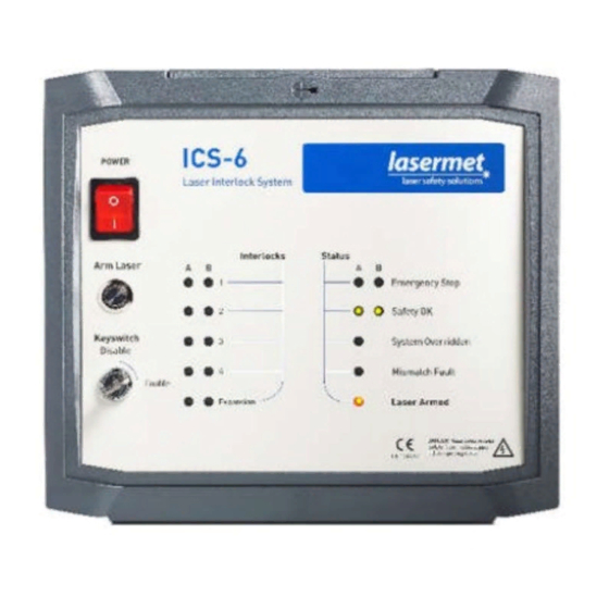
- Page 1 ICS Contactors Wiring Manual LASERMET WIRING CONTACTORS TO AN ICS-5 OR ICS-6 WIRING MANUAL Issue 2 01518-53-000 Issue 2 13 January 2020...
- Page 2 ICS Contactors Wiring Manual LASERMET ICS Contactors Wiring Manual Contents Safety Warnings ........................3 Concept ..........................4 Testing ..........................6 Specifications ........................7 Warranty ..........................7 Contact Details ........................8 01518-53-000 Issue 2 13 January 2020 Page 2 of 8...
- Page 3 ICS Contactors Wiring Manual Safety Warnings This device is intended to be used as part of a safety system which may be used to protect personnel and equipment from possible injury, damage, or loss. As such it must be installed and wired according to these instructions and tested by suitably qualified persons.
- Page 4 The earth must not be switched through the contactors. It is then necessary to run either one 6-core or two 4-core cables between the ICS-5 / ICS-6 and the contactor box. These cables will carry low current 24V control signals, and cables with 7/0.2mm stranded copper cores are ideal.
- Page 5 Full support, design and installation is available from Lasermet, please contact us for any queries. Contact details are given at the end of this manual.
- Page 6 ICS Contactors Wiring Manual Testing Testing should only be undertaken by a qualified electrical engineer. A suitably rated tester is required to verify presence/absence of mains electrical power on the contactor terminals and any socket outlets or load equipment connected to the contactor output. During the tests hazardous voltages will be present inside the contactor box and on controlled outlet sockets or load equipment.
- Page 7 180mm wide X 182mm high X 163mm deep Dimensions are approximate. Values given as ‘typical’ are average values measured across a number of samples and are not guaranteed. Lasermet reserve the right to alter any specification without prior notice. Warranty Lasermet provide a 12-month warranty for defects in materials and manufacture, from the date of installation or delivery.
- Page 8 ICS Contactors Wiring Manual Contact Details Lasermet provide a full range of laser interlock equipment including interlock switches, illuminated warning signs, laser shutters, entry keypads with built-in fail-safe override timer, door locks, external power supplies etc. which can be interconnected to provide a complete system. We also supply equipment and consultancy covering all aspects of laser safety.


Need help?
Do you have a question about the ICS-5 and is the answer not in the manual?
Questions and answers