
Related Manuals for Lasermet ICS-LJIM


Summary of Contents for Lasermet ICS-LJIM
- Page 1 LJIM Instruction Manual LASERMET LASER JAILMASTER INSTRUCTION MANUAL FAIL SAFE LASER INTERLOCK CONTROLLER AND ACTIVE BEAMGUARD INTERFACE 02116-53-001 Issue 3 19 January 2021...
-
Page 2: Table Of Contents
LJIM Instruction Manual LASERMET ICS-LJIM Instruction Manual Contents Declaration of Conformity ....................4 Safety Warnings ........................5 Concept ..........................6 Summary of Evaluation of Compliance to EN ISO 13849-1:2015 ........7 Installation .......................... 8 Positioning ........................8 Front Panel ........................8 Wiring .......................... - Page 3 LJIM Instruction Manual Serial Interface ......................21 11.1 Connections ......................21 11.2 Modbus Operation ....................22 11.3 Register Access ...................... 23 11.4 Example using Python ................... 25 Connecting Expansion Units to ICS-7-OEM ..............27 Fuses ..........................27 Specifications ........................ 28 14.1 Main Unit .......................
-
Page 4: Declaration Of Conformity
DECLARATION OF CONFORMITY This is to certify that the Laser Jail Master and Son of Laser Jail Master Expansion Board designated by Lasermet Part Number ICS-LJIM and ICS-LJIM-SO respectively has been tested in accordance with the following standards and found to comply. -
Page 5: Safety Warnings
LJIM Instruction Manual Safety Warnings This device is intended to be used as part of a safety system which may be used to protect personnel and equipment from possible injury, damage, or loss. As such it must be installed and wired according to these instructions and tested by suitably qualified persons. -
Page 6: Concept
Some of these can be used to support the LJIM system. Full support, design and installation is available from Lasermet; please contact us for any queries. Contact details are given at the end of this manual... -
Page 7: Summary Of Evaluation Of Compliance To En Iso 13849-1:2015
LJIM Instruction Manual Summary of Evaluation of Compliance to EN ISO 13849-1:2015 To achieve a complete system performance level ‘e’ the system must be wired as described in this manual using suitably rated door sensors and measures taken to minimise the effects of common cause failures in the sensors and wiring which may be connected to the unit. -
Page 8: Installation
LJIM Instruction Manual Installation The LJIM is designed to be attached to a 35mm ‘top-hat’ style DIN rail inside a control cabinet. It should always be enclosed in a cabinet that requires use of a tool or key to open to prevent tampering and risk of touching live connections. -
Page 9: Wiring
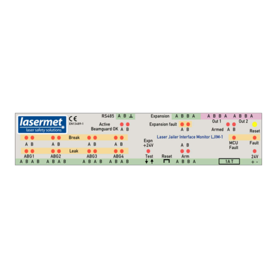
The dual-channel ABG inputs are wired A-B-A-B to maximise the detection of wiring errors. The other dual-channel inputs and outputs are wired A-B-B-A in line with Lasermet’s normal practice. Input signals are indicated by a green background, while the interlock outputs have a pink background. -
Page 10: Ljim Inputs
Lasermet provide a range of small distribution boxes which allow for convenient positioning of wall or surface-mounted plugs for laser interlocks and sockets for shutters. The boxes are available with different combinations of plugs and sockets. -
Page 11: Shutter With Own Power Supply
The LS-20 and LS-200 Shutters can use the above circuit. However, if monitoring of the shutter state is required it is recommended that the ICS-7-OEM controller, which has monitoring inputs, is used. Please contact Lasermet for further details. 6.4 Shutter with own Power Supply For shutters that have their own power supply or are to be run from an existing supply, you can use one of the controller outputs to operate them. -
Page 12: Interlock Connectors
For lasers with dual channel interlocks use the following connections: Where the laser may be removed from the system or exchanged, a Lasermet Distribution Box may be used to provide a connection point convenient to the laser. In this case for lasers with a single channel interlock, the A and B LJIM output channels are connected in series to pins 1 and 2 of the plug of the distribution box. -
Page 13: Electromagnetic Door Locks
In all cases a diode rated at 1A 50V or more must be wired directly across the terminals of each door lock. Lasermet’s Maglocks usually have the diode fitted as standard, in which case it is essential that the supply is connected the right way round. -
Page 14: Expansion Units
LJIM Instruction Manual Expansion Units The LJIM can be connected to one or more Lasermet Laser Jailer Expansion Units which extend the main unit by providing more ABG monitor sections. The signalling from the expansion units is provided by dual relay contacts. Essentially there is no limit on the number of contacts that can be connected, since the resistance of each individual contact is so low. -
Page 15: Connections To Expansion Units
LJIM Instruction Manual 7.2 Connections to Expansion Units The diagram shows the connections for two expansion units. The dual-channel outputs are daisy- chained to the expansion input on the LJIM. Further expansion units can be added, keeping their output contacts in series. The test connections are made in the same manner. The two test terminals on the expansion units are actually connected together, but two terminals are provided to facilitate wiring as a continuous loop. -
Page 16: Mismatch Detector
LJIM Instruction Manual Mismatch Detector The LJIM trips out and disables the laser when either of its two safety circuits opens. It is normal for both safety circuits to open more or less simultaneously. If the second safety circuit does not open within a short time of the first (typically around 1.5 seconds), a mismatch is triggered and the ‘Fault’... -
Page 17: Clearing A Mismatch Fault Indication
‘reset’ switch should have a contact which closes to reset the detector. This could be provided by a switch or a volt-free output from a PLC. Contact Lasermet or your local distributor for assistance if you wish to use this feature. 02116-53-001... -
Page 18: Led Indicators
LJIM Instruction Manual LED Indicators ABG Status LEDs Four LEDs are provided for each of the ABG monitors on the LJIM and expansion units. These indicate ‘break’ and ‘leak’ conditions for each channel respectively. If a track on the ABG window or panel is broken, the corresponding ‘break’ LED will illuminate. This is the usual fault condition after a laser strike. - Page 19 LJIM Instruction Manual 'Armed' LED’s When the 'Active Beamguard OK' LEDs are lit and the external Arm contacts have been closed, the 'Armed' LEDs will light orange to warn that the LJIM has enabled the laser. If the ‘Active Beamguard OK’...
-
Page 20: Operation
LJIM Instruction Manual Operation Once correctly wired, the LJIM is extremely easy to use. The following instructions cover the most common arrangements. For more complex customer-specific systems, additional procedures may apply. 10.1 Starting Up 1. Apply 24V power to the controller. 2. -
Page 21: Serial Interface
LJIM Instruction Manual Serial Interface The LJIM is fitted with a serial interface to facilitate indication of the ABG and arm status. This takes the form of an RS485 physical interface configured to act as a Modbus RTU slave unit. The interface specification is as follows: Physical Interface RS485... -
Page 22: Modbus Operation
This can be a dedicated Modbus master, a PLC with Modbus master capability, a PC with a USB-to-RS485 adapter, running Modbus master software, or a custom status display. For further details of master options, please contact Lasermet. A PC example is given in a later section. Device Address Each slave device has a device address, which is used by the master to select a slave. -
Page 23: Register Access
LJIM Instruction Manual 11.3 Register Access Reading Status Registers The two status registers are mapped as input registers 30000 and 30001, and also duplicated as holding registers 40000 and 40001. This should enable all the available master devices to read the registers. - Page 24 LJIM Instruction Manual The registers are read by sending a ‘read input registers’ or ‘read holding registers’ command. This is an example query (the base address offset of 30000 or 40000 is implicit, and all numbers are hexadecimal): Slave Address addr Function Starting address high...
-
Page 25: Example Using Python
LJIM Instruction Manual This command can also be sent using function 16 (10 hex). This command is normally used to write multiple registers but is enabled to allow a wider range of master devices. The above example, implemented as function 16, would look like this: Slave address Function Starting address high... - Page 26 LJIM Instruction Manual The unit has responded with a value indicating that the outputs are off and there are no faults. Similarly, we can read the ABG status register: >>> lj.read_register(0,0,4) >>> 65535 >>> The result (returned here in decimal) indicates that all status bits are 1. To set a new slave address: >>>...
-
Page 27: Connecting Expansion Units To Ics-7-Oem
The outputs of the expansion units are daisy-chained and connected to the E-stop interlock input on the ICS-7-OEM. It is not recommended to connect the ICS-LJIM-SO outputs to an interlocked door input. In this case, the 'doors closed' output from the ICS-7-OEM will open contact when the LJIM-SO does its self-checking. -
Page 28: Specifications
210mm wide X 90mm high X 55mm over DIN rail Weight 0.26kg Dimensions are approximate. Values given as ‘typical’ are average values measured across a number of samples and are not guaranteed. Lasermet reserve the right to alter any specification without prior notice. 02116-53-001 Page 28 of 30... -
Page 29: Warranty
LJIM Instruction Manual Warranty Lasermet provide a 12-month warranty for defects in materials and manufacture, from the date of installation or delivery. Installations completed by Lasermet are covered against defects in workmanship for 12 months. Damage or defects caused by other factors are not covered. For example, industrial contamination, incorrect cleaning, storm damage. -
Page 30: Contact Details
LJIM Instruction Manual Contact Details Lasermet provide a full range of laser interlock equipment including interlock switches, illuminated warning signs, laser shutters, entry keypads with built-in fail-safe override timer, door locks, external power supplies etc. which can be interconnected to provide a complete system. We also supply equipment and consultancy covering all aspects of laser safety.
Need help?
Do you have a question about the ICS-LJIM and is the answer not in the manual?
Questions and answers