
Subscribe to Our Youtube Channel
Related Manuals for Lasermet ICS-6


Summary of Contents for Lasermet ICS-6
- Page 1 ICS-6 Instruction Manual LASERMET ICS-6 INSTRUCTION MANUAL FAIL SAFE LASER INTERLOCK CONTROL SYSTEM 01000-53-000 Issue 11 19 January 2021...
-
Page 2: Table Of Contents
Summary of Evaluation of Compliance to EN ISO 13849-1:2015 ..........8 Installation ..........................9 Wiring ...........................10 Mains In ........................10 5.1.1 ICS-6 (110V to 240V ac 50-60Hz) ................10 5.1.2 ICS-6-24 (24VDC) ......................11 ICS-6 Inputs ........................11 5.2.1 Mechanical Interlock Switches .................11 5.2.2 Coded Magnetic Interlock Switches .................14 5.2.3 Emergency Stop and Break Glass Switches ..............14... - Page 3 ICS-6 Instruction Manual 5.5.3 Override Switch without Timer ................27 5.5.4 Local Override ......................27 5.5.5 Override Alarm ......................28 Typical Installation .......................28 Expansion Boards .........................30 Introduction........................30 Installing Expansion Boards ..................31 Mismatch Detector ......................33 Description ........................33 Configurable Options for Safety Circuit Mismatch Events ...........33 Clearing a Mismatch Fault Indication ................34...
-
Page 4: Declaration Of Conformity
INTERLOCK CONTROL PANEL ICS-6 Drawing Number 01000-00-000 DECLARATION OF CONFORMITY This is to certify that the ICS-6 Interlock Control Panel designated by Lasermet Drawing Number 01000-00-000 has been tested in accordance with the following directives and standards and found to comply. -
Page 5: Concept
The master system can prevent the ICS-6 and its associated laser from being armed. The ICS-6 can be linked to a fire alarm so that the laser is disarmed, and any controlled doors are unlocked in the event of an alarm. - Page 6 ICS-6 to provide a complete system. Full support, design and installation is available from Lasermet, please contact us for any queries. Contact details are given at the end of this manual.
-
Page 7: Safety Warnings
If the equipment is used in a manner not specified by Lasermet, the protection provided by the equipment may be impaired. -
Page 8: Summary Of Evaluation Of Compliance To En Iso 13849-1:2015
Summary of Evaluation of Compliance to EN ISO 13849-1:2015 Note that this summary relates to the ICS-6 controller only. To achieve a complete system performance level ‘e’ the system must be wired as described in this manual using suitably rated door sensors and measures taken to minimise the effects of common cause failures in the sensors and wiring which may be connected to the unit. -
Page 9: Installation
Care should be taken in the running of conduits that the proposed entry position in the ICS-6 can be accommodated and that the front cover of the ICS-6 can be opened. -
Page 10: Wiring
The ICS-6 is a versatile interlock system and there are a variety of ways in which it can be used. Be sure you know which configuration you require before you attempt to wire the unit. If you require further assistance, please call Lasermet technical help. -
Page 11: Ics-6-24 (24Vdc)
5.2.1 Mechanical Interlock Switches Up to four door interlock switches may be directly wired to the ICS-6. By making external connections, more switches can be added and arranged in groups for indication purposes. The interlock switches are wired to the terminals labelled INTERLOCK 1 through to INTERLOCK 4. - Page 12 Interlock switches need to be fitted to both, and the two doors can then be wired together so that a single monitor indication light will illuminate on the front panel of the ICS-6 if either of the doors is open. The switches in a group should be wired with their safety contacts in series.
- Page 13 This relies on successful operation of the door switch and contact failures are not detected. The ICS-6 mismatch detector should be disabled if this arrangement is used. The example shows a system with two doors.
-
Page 14: Coded Magnetic Interlock Switches
The Lasermet IS-MDC-12 is a dual channel magnetic door switch. If the mismatch detector is used in the ICS-6, any single contact failure in the door switch will be detected and the laser inhibited. In this switch the red and blue wires are taken to the ‘A’ terminals and the black and white wires to the ‘B’... -
Page 15: Master Control And Connection To Fire Alarm
Master Control and Connection to Fire Alarm The ICS-6 has the option of being remotely ‘locked out’ by a remote master switch or a master interlock system. For a dual channel system required to perform to ISO13849 performance level ‘e’, the remote switch should have two contacts which close to enable the laser. -
Page 16: Ics-6 Illuminated Sign Control Output
Signs. These signs must not be connected to the mains supply. Option 1 One-way Illuminated Sign The warning sign will come on as soon as the mains switch of the ICS-6 is turned on. Option 2 One-way Illuminated Sign The warning sign will come on when the ‘Arm Laser’ button is pressed. - Page 17 Two-way Illuminated Warning Sign The first warning sign will come on when the ICS-6 mains switch is turned on. The first warning sign will go off and the second warning sign will come on when the ‘Arm Laser’ button is pressed. Note that in the case of the Lasermet Miniature Warning Sign, both indications are displayed in the same unit.
-
Page 18: Interlock Operator Output Contacts
There is a 9-contact upgrade option should three contacts prove insufficient, please contact Lasermet or your local distributor if this is required. The wiring space is very constrained when the 9- contact board is fitted, and it is normally recommended that the deep-case option is also selected which increases the overall depth of the ICS-6 from 89mm to 145mm. -
Page 19: Beam Shutters
(12 VDC 0.8 A maximum or 24 VDC, 3 A maximum) The ICS-6 has a built-in DC supply for operating laser shutters and is able to provide both continuous and switched supplies using one of the Interlock Operator outputs. Several shutters of the same type may all be powered from one Interlock Operator contact, please contact Lasermet for details if required. - Page 20 LS-20 Shutter The LS-20 Shutter can use the above circuit set to 24VDC. However, it is recommended that the monitoring circuit shown below is included to allow the ICS-6 to monitor the shutter and to detect any faults. If using the LS-20 SIL3 twin shutter the circuit below must be used to achieve the SIL3 / PL ‘e’ rating.
- Page 21 ICS-6 Instruction Manual The LS-20 Shutter has its own distribution socket. The wiring connections inside the distribution box are shown below: CONTROL +24V SUPPLY MONITOR +24V SUPPLY REMOTE OPEN 24V INPUT OPEN STATUS 24V OUTPUT CLOSED STATUS 24V OUTPUT MONITOR CONTACT 1 OPEN...
-
Page 22: Interlock Connectors
Furthermore, some lasers also include one or two ‘laser safe’ contacts which can be monitored by the ICS-6. In this instance if either or both ‘laser safe’ contacts are not closed the ICS-6 will set illuminated warning signs to the danger indication and inhibit arming of the laser. -
Page 23: Electro Magnetic Door Locks
5.4.4 Electro Magnetic Door Locks Use only fail-safe door locks provided by Lasermet (electric door strikes or maglocks). These will prevent access to the room while the laser is on while always allowing people to enter or leave the room in the event of a power loss. In order to ensure that people can always enter or leave the room in the event of an emergency it will be necessary to put an emergency stop or break glass switch near each door. - Page 24 ICS-6 Instruction Manual Note that the total combined current available from the 24V and 12V outputs from the ICS-6 is 4A, and the maximum current from the 12V output is 1A, so whilst both shutters and door locks may be used at the same time, care should be taken not to exceed this rating in total.
-
Page 25: Override
Ensure that the jumper link J6 ‘O/RIDE CTRL’ on the ICS-6 Main Circuit Board is closed across both pins so that the keypad can operate the Override circuit inside the ICS-6. The diagram below shows the circuit where a lock is provided on the door. If no lock is provided this part of the circuit may be omitted, and the keypad may be programmed not to activate the door relay and ‘Door Unlocked’... -
Page 26: Override Switch With Timer
The Override board must be fitted to the ICS-6 by inserting the male connector on the plug-in board into the female connector near the bottom of the main board of the ICS-6 on the back of the door. Align the hole in the Override board with the peg on the ICS-6 main board and insert the screw and washer to secure it in position. -
Page 27: Override Switch Without Timer
The third contact is connected between the terminal marked ‘O/R’ and the terminal marked ‘+24V’ on the ‘KEYPAD’ terminal block J7. An Override Timer Board must not be fitted to the ICS-6, and the link ‘J6 Override Control’ must be removed to prevent the non-overridden door contacts from being defeated. -
Page 28: Override Alarm
Override Alarm There is an audible Override alarm inside the ICS-6 which is enabled when the BUZZER CTRL link J4 is closed on the main PCB. There is also an audible alarm on the Override board (if fitted) which is enabled by closing link 10. - Page 29 ICS-6 Instruction Manual 01000-53-000 Page 29 of 42 Issue 11 19 January 2021...
-
Page 30: Expansion Boards
If the laser burns through the tile it is shut down before it burns through the enclosure. The fail-safe Interface is able to monitor up to 1000 tiles and the ICS-6 is able to automatically test the operation of the tiles and the interface each time the system is armed. -
Page 31: Installing Expansion Boards
6.2 Installing Expansion Boards It is possible to install one expansion board into a standard ICS-6, however the space for wiring is fairly restricted so a deep case option is available for ICS-6 which increases the depth of the unit from 89mm to 145mm, which gives ample space for three or four expansion boards. - Page 32 ICS-6 Instruction Manual Expansion Board Expansion Socket Terminator Ensure Screws are fitted 01000-53-000 Page 32 of 42 Issue 11 19 January 2021...
-
Page 33: Mismatch Detector
Mismatch Detector 7.1 Description The ICS-6 trips out and disables the laser when either of its two safety circuits opens. If all the door interlock and emergency stop switches have two contacts, one in each safety loop, then it is normal for both safety circuits to open more or less simultaneously. -
Page 34: Clearing A Mismatch Fault Indication
If the ICS-6 has been configured to permanently lock out, it can only be reset by opening the unit, turning on the power and pressing the ‘RESET’ button SW1 on the Control Board. This should only be undertaken by suitably qualified technicians once the fault has been identified and repaired as otherwise the unit will just lock out again. -
Page 35: Remote Test And Reset
The ‘test’ switch should have a contact which is normally closed, and which opens to perform the test. The ‘reset’ switch should have a contact which closes to reset the detector. Contact Lasermet or your local distributor for assistance if you wish to use these features. 01000-53-000... -
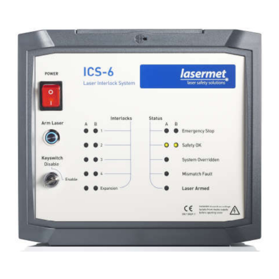
Page 36: Led Indicators
Please see the ‘Mismatch Detector’ section. ‘EXPN’ LEDs The ICS-6 may have one or more expansion boards fitted internally (see section 6), and the status of the board(s) is indicated. The LED’s are illuminated yellow if an expansion board has opened the ICS- 6 safety circuits. - Page 37 When the 'Safety Circuit Complete' LED has lit and the Arm Laser button has been pressed, the 'Laser Armed' LED will light orange to warn that the ICS-6 has enabled the laser. If the ‘Safety Circuit Complete’ LED is illuminated but the ‘Laser Armed’ LED does not illuminate when the Arm Laser button is pressed, this could indicate that the internal checking circuitry of the ICS-6 has detected a fault condition.
-
Page 38: Operation
9.2 Resuming Operation after an Interlock Switch has been opened When any interlocked door is opened or the emergency stop button is activated, the ICS-6 will cut the power to the laser or the shutters. To resume laser operation: 1) Close all interlocked doors (where necessary). Note LED state on front panel. -
Page 39: Using The Override
The system will now go into override mode for a short time, and a buzzer will sound. Note. If any of the interlock switches are still open when the timed override expires, the ICS-6 will cut the power to the laser or shutters. -
Page 40: Specifications
263mm wide X 233mm high X 145mm deep (deep box) Weight 1.7kg (standard) Dimensions are approximate. Values given as ‘typical’ are average values measured across a number of samples and are not guaranteed. Lasermet reserve the right to alter any specification without prior notice. 01000-53-000 Page 40 of 42... -
Page 41: Warranty
ICS-6 Instruction Manual Warranty Lasermet provide a 12-month warranty for defects in materials and manufacture, from the date of installation or delivery. Installations completed by Lasermet are covered against defects in workmanship for 12 months. Damage or defects caused by other factors are not covered. For example, industrial contamination, incorrect cleaning, storm damage. -
Page 42: Contact Details
ICS-6 Instruction Manual Contact Details Lasermet provide a full range of laser interlock equipment including interlock switches, illuminated warning signs, laser shutters, entry keypads with built-in fail-safe override timer, door locks, external power supplies etc. which can be interconnected to provide a complete system. We also supply equipment and consultancy covering all aspects of laser safety.
Need help?
Do you have a question about the ICS-6 and is the answer not in the manual?
Questions and answers