
Related Manuals for IT Concepts iRis DVR X

Summary of Contents for IT Concepts iRis DVR X
- Page 1 iRis iRis Videoendoskop Videoendoskop Videoendoskop Operation Manual Operation Manual...
-
Page 4: Table Of Contents
Content Introduction ........... 5 Creating and saving Image Captures Choosing a Standard Setting ......... 24 Warning Notices and Precautions ..6 Inserting Text ............25 Scope of Delivery ........8 Image Capture and Video Recording System Presentation in Mode „OFF“ ............26 Overview iRis ............ -
Page 5: Introduction
Introduction We congratulate you on buying your iRis DVR Industrial Videoscope, in the following just named iRis. It unites Light Source, TFT Display plus Image Storage and Video Recording Device. The diversity of inspection objects, materials and lightning conditions often makes it difficult to get high-quality images. -
Page 6: Warning Notices And Precautions
Warning Notices and Precautions Read the Operation Manual care- Caution! Never look directly into the light fully before using the iRis. emitting part of the iRis. It can cause injuries of eyes. Always switch off the Light Source Caution! The iRis has to be employed by before changing, controlling or cleaning the skilled and qualifi... - Page 7 The iRis is an electric device and must not withdrawal point. Of course batteries and ac- be disposed in domestic waste. Pursuant to cumulators you got from IT Concepts can be European Directive 2002/96/EG on waste handed or sent to us.
-
Page 8: Scope Of Delivery
2004/108/EG unter Bezugnahme der 269-46040-0000-I harmonisierten Norm EN61326-1 (2006) Emission- und Störfestigkeit. 269-48015-0000-I 269-48020-0000-I 269-48030-0000-I 269-48040-0000-I Lahnau, 31. Januar 2011 IT Concepts GmbH Frank Schlagenhauf Gewerbestrasse 17 www.itcworld.com Manager Product Development D-35633 Lahnau info@itcworld.de ITC Case Pocket Neck Holder... -
Page 9: System Presentation
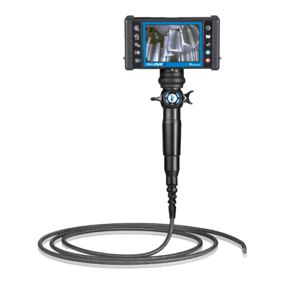
System Presentation SD Card Slot Edge Protector (under Edge Protector) Control Panel Control Panel 12,7cm (5“) TFT VGA Colour Display Pins for Neck Holder Bedienhebel Lever (left/right) oben/unten lock the articulating head of the Live and saved images as well as probe in the desired position during video recordings are shown on the inspections. - Page 10 Presentation Pins fpr sunshield Pins fpr sunshield Battery Compartment ON/OFF LED Light Source Swivel Lock Mechanism Cinch OUT, 12V DC Plug external display, etc. Capture Button Handle The region to be inspected has increases the durability of the fl exible to be that large that movements probe.
-
Page 11: The Control Panel
System Presentation The Control Panel Using the control panel you can navigate through the menu structure, select and confirm functions. Navigation up Power Digital Zoom in Digital Zoom out Memory (open/close Navigation down memory mode) Menu (open/close OK-Button / Enter on-screen menu) Navigation left Capture / Freeze... -
Page 12: Charging The Battery
System Presentation Cover Battery Compartment Battery Charging the Battery Battery Compartment Before charging please pay attention to the included manual for the charger. For charging the accumulator has to be removed from the housing. For this the cover of the battery compartment has to be detached by releasing the locking screw. -
Page 13: Working With Mains Supply
Preparing the iRis Working with external Power Supply As an option the iRis can be powered as follows: 1) AC Adapter + Power Supply Cable 2) PowerBelt 3) Car Battery Cable 4) Cigarette Lighter Cable Note: The 12V DC plug as well as the socket is marked with a red dot. -
Page 14: Inserting The Sd Card
Preparing the iRis Inserting the SD Card Slightly remove the right edge protector and put a formatted SD Card (32GB max.) into the card slot. The SD Card included in the scope of delivery is already inserted and properly formatted. If the SD Card is not formatted you have to format it as described on page 17. -
Page 15: Starting Inspection
Starting Inspection Switching-on the iRis After having prepared the iRis according this operation manual switch it on by pressing POWER. Please inspect the iRis probe as described on page 40 before inserting the endoscope into the inspection object! Status Indicator Line At start-up the iRis always is in Live Mode. -
Page 16: Language Selection
Starting Inspection Language Selection If you want to change the language set proceed as At delivery status the iRis should already be set to follows: your language or to English. • MENU At initial operation you should check if the appropriate •... -
Page 17: Format Sd Card
Starting Inspection Format SD Card Image Control Camera Control The SD Card delivered with the iRis is already Annotation formatted. To format a SD Card proceed as follows: Dimension System Setting System Setting Press MENU, select menu item System Setting and Safety remove SD press OK. -
Page 18: Setting Time And Date
Starting Inspection Setting Time and Date Image Control Camera Control In the delivery status time and date should already Annotation be set. Dimension System Setting System Setting At initial operation you should check time and date Safety remove SD and set them if necessary. If you want to change time and/or date proceed as follows: Status Line... -
Page 19: Resetting To Default Settings
Starting Inspection Resetting to Default Settings Image Control Camera Control By selecting the menu item Fabric Settings all Annotation manually changed and adjusted parameters can be Dimension put back to factory setting, except for date, time and System Setting System Setting text generator. -
Page 20: Image Control
Starting Inspection Image Control Image Control Image Control Camera Control Image parameter (brightness, contrast and colour as Annotation well as zoom and image flip) can be adjusted under Dimension Image Control in the menu. System Setting Safety remove SD Change the select parameter by using the arrow keys. New settings will immediately be effective. -
Page 21: Turning The Display
269-48020-0000-I 269-48030-0000-I On the image the levers are shown in „neutral“ home 269-48040-0000-I position. In this position the articulation section is Lahnau, 31. Januar 2011 straighten. IT Concepts GmbH Frank Schlagenhauf Gewerbestrasse 17 www.itcworld.com Manager Product Development D-35633 Lahnau info@itcworld.de... -
Page 22: Passing Covings
Starting Inspection Fig. A Passing Covings Carefully push the probe to the beginning of the Size and covings of the object to be inspected have coving while observing on the display. to be large enough to allow the movements of the Fig. -
Page 23: Retracting The Endoscope
iRis Starting Inspection The innovative Videoscope Retracting the Endoscope To retract the endoscope the articulating section has to be straighten fi rst, i.e. the levers have to be put to neutral position. By observing on the display and appropriate movement of the levers an equal distance of the distal end to the walls of the cavity has to be kept. -
Page 24: Creating And Saving Image Captures
Creating and saving Image Captures and Video Recordings Choosing a Standard Setting Image Control Camera Control There are two standard settings available. Decide Annotation whether you want to work in Mode Freeze Frame ON Dimension or OFF for image captures and video recordings (see System Setting System Setting pages 27-29) before starting the inspection. -
Page 25: Inserting Text
Creating and saving Image Captures and Video Recordings Inserting Text Image Control Camera Control With the text generator you have the possibility to Annotation Annotation mark all images with a text commentary (a single line Dimension of 31 characters). Please insert text before saving the System Setting image. -
Page 26: Image Capture And Video Recording In Mode „Off
Creating and saving Image Captures and Video Recordings Standard Setting Nr. 1 „Freeze Frame OFF“ Direct Image Video Capture Recording Start / Stop During recordings single images can be saved as follows:... -
Page 27: Image Capture And Video Recording In Mode „On
Creating and saving Image Captures and Video Recordings Standard Setting Nr. 2 „Freeze Frame ON“ Direct Image Capture Push 1 x Image freezes Image freezes Save Frozen is displayed Frozen is displayed Image on the screen on the screen 1 x short push 1 x long push 1 x short push 1 x long push... - Page 28 Video Recording Push 1 x Start Text - Optionally recording insert in advance (see page 26) 1 x short push 1 x short push Press 1 x Press 1 x Start/Stop Pause/Continue Pause/Continue Save Save recording recording recording image image Press 1 x Stop recording...
-
Page 29: Comparative Measuring With The Iris
EC Declaration o iRis DVR Calibrating and Comparative Measuring with the iRis iRis iRis The Videoscope The innovative Videoscope The iRis provides the possibility of point-to-point in Live Mode with visible flags. Now you may save measuring within the image. This can be used in the as usual (see pages 27-29). -
Page 30: Playback Of Saved Images And Video Recordings
Resolution: 800 x 600 pixel LOCATION: Folder HVR IT CONCEPTS INSPEKTION Name: Attention! You are able to create and name new All fi les (image as well as video recording) are named folders on the removable media by connecting a card by the system. - Page 31 Playback of saved Images or Video Recordings How to access fi les. Note! The LED Light Source is automatically switched-off in Memory Mode and reactivated when Press MEMORY to access the Browser Mode. changing to Live Mode again. Navigate through the folder structure to the desired fi le by using the arrow keys and the OK button BROWSER /SD/...
- Page 32 Playback of saved Images or Video Recordings Images Video Recordings After having accessed the desired fi le you can con- After having accessed the desired fi le you can trol it as follows by using the arrow keys and the OK control it as follows by using the arrow keys and the button: OK button:...
-
Page 33: Optimising Camera Settings
Optimising Camera Settings Camera Setting Image Control Camera Control Camera Control The camera settings help to optimal adjust the Annotation videoscope or camera to your application to get Dimension perfect images. System Setting Safety remove SD The iRis System provides two camera settings: STANDARD INTEGRATION Kameraeinstellung Standard... -
Page 34: Camera Setting Standard
Optimising Camera Settings Camera Setting STANDARD White Balance The standard setting is approved for a variety of The white balance can only be executed in the camera applications to get clear and expressive inspection setting STANDARD. images. How colours of an image or video recording are This setting produces an automatic optimising of the displayed is depending on the colour temperature of camera settings. -
Page 35: Camera Setting Manual
Optimising Camera Settings Camera Setting Manual shutter MANUAL Setting image brightness by adjusting the relative exposure time of the sensor. This allows image The camera setting Manual gives you the possibility capture at poor lighting conditions. to individually change the camera setting without the influence of the automatic camera control system. -
Page 36: Cleaning And Care
269-48030-0000-I 269-48040-0000-I The distal end has to be cleaned with cotton swabs Lahnau, 31. Ja (Q-Tip®) soaked with high-proof alcohol. Do not use rough cloths for cleaning! IT Concepts GmbH Frank Schlage Gewerbestrasse 17 www.itcworld.com Manager Prod D-35633 Lahnau info@itcworld.de... - Page 37 ±100° in the horizontal plane. Bring the lever back to the home position afterwards and release it. At occurrence of any problem stop operating and contact the Customer Service of IT Concepts (see page 43).
-
Page 38: Transport And Storage
Transport and Storage System Transport and Storage The System needs to be dry and cleaned for storage. The levers have to be brought to neutral position. Carefully insert the probe into the reel in the case. Push the probe slowly into the reel until you are able to place the housing in the corresponding recess without bending the probe. -
Page 39: Spare Parts And Accessories
Spare Parts and Accessories iRis Accessories SD Memory Card Neckholder iRis DVR Clamp Li-Ion rechargeable Battery NC2040A24 Charger for Li-Ion rechargeable Battery NC2040A24 iRis AC Adapter 12V DC / 5,50A iRis Case Lens Box for Objective Lenses ITC Case Pocket... -
Page 40: Service
Fax: + 49 (0) 6441 679299 - 99 Video Format: AVI (.avi) Image Format: BMP (.bmp) Storage: SD-HC-Memory Card up to 32GB (FAT32) IT Concepts GmbH Camera Control Gewerbestr. 17 Image Sensor: Advanced image Sensor Camera Control / Exposure: Integration modes: Automatic, Short, Long, Manuell... - Page 41 Technical Specifi cations Chip on the tip Illumination LED on the tip Type: High-Power Whitelight-LED´s with fi ber optic light guides (6mm) Illumination Control: 3-steps Colour Temperature: ca. 6500k Average Lamp Lifetime: ca. 5000h Probe Diameter: 4.0mm 6.0mm Working Length: 4.9 - 13.1ft (1.5 - 3.0m) 4.9 -13.1ft (1.5 - 7.5m) 4.0mm 6.0mm...
- Page 42 Notes...
- Page 44 © 2011 IT Concepts GmbH. All rights reserved. This Operation Manual corresponds to the status at the time of going to print. IT Concepts accepts no liability for any printing errors contained herein. Design subject to change. We reserve the right of making technical changes at any time. No sections of this Operation Manual may be reprinted, photo-mechanically, mechanically or digitally copied or reproduced without the express approval of IT Concepts GmbH.
Need help?
Do you have a question about the iRis DVR X and is the answer not in the manual?
Questions and answers