Advertisement
Available languages
Available languages
Quick Links
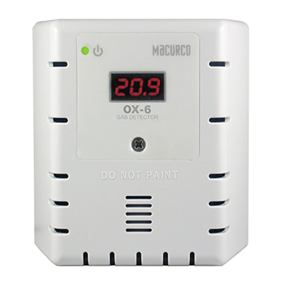
Macurco
6/12 Series
TM
Gas Detector and Controller
Installation Manual
Please refer to Product Operation Manual for additional product information and
features.
NOTE: Read and understand the User Instructions before installing and operating
this product. Refer to page 7 to access the User Instructions.
1.
Safety
Installation must comply with recognized standards of the appropriate authority
in the country and concerned locality.
2.
Use Instructions and Specifications
NOTE: Macurco 6/12 Series detector are not intended for use in hazardous
locations. Please refer to product full operating instructions for details on
application of each detector.
Product
Gas Detected
CM-xx
Carbon Monoxide (CO)
TX-xx-ND
Nitrogen Dioxide (NO2)
GD-xx
Combustible (Default: Methane)
TX-xx-AM
Ammonia (NH3)
TX-xx-HS
Hydrogen Sulfide (HS)
RD-xx
Refrigerant (REF)
OX-xx
Oxygen (O2)
CD-xx H/MC
Carbon Dioxide (CO2)
CD-6B
Carbon Dioxide (CO2)
CD-6G
Carbon Dioxide (CO2)
CX-xx
Carbon Monoxide and Nitrogen
Dioxide
xx – 6 (for low voltage detector) or 12 (for line voltage detector)
ETL LISTED to UL 61010-1, Certified to CSA C22.2#61010-1
To access the complete manual, go to
www.macurco.com
below:
Macurco Gas Detection
3601 N. St. Paul Avenue
Sioux Falls, SD 57104
Technical Support Contact Information
Phone: 1-844-325-3050
Fax : 605-951-9616
Email:
support@macurco.com
Website:
www.macurco.com/support/
General Contact Information
Phone: 1-877-367-7891
Fax: 605-951-9616
Email:
info@macurco.com
Web site:
www.macurco.com
Rev – 1.1
Issue Date: 12-09-2020
Document No: 34-2900-0513-8
© Aerionics 2019. All rights reserved.
Macurco is a trademark of Aerionics, Inc.
Specifications
Dimensions
Shipping weight
Color
Power Supply
Input voltage
and Power
Operating Environment
Temperature
Humidity and
Atmospheric Pressure
Installation
Connections
Mounting box
Features
Digital display
(Range)
Buzzer
0-200 ppm
*Alarm Relay
0-20 ppm
*Fan Relay
0-50 %LEL
**Alarm 1 and 2 Relay
0-100 ppm
**Alarm 3 Relay
0-50 ppm
*
All models except CD-6B.
0-1000ppm
**CD-6B only
0-25% vol
0-5000 ppm
3.
Installation
0-5.00% vol
Refer to product manual for coverage of the detector and installation location.
0-5.00% vol
NOTE: De-energize Power during installation and wiring. Use 12 to 22 AWG wire.
CO: 0-200 ppm
Mounting - The device mounts on a 4" square (or 4x4) electrical box. Do not
NO2: 0-20 ppm
mount the device inside another box, unless it has good air flow through it.
Power Supply - Use Class 2 power supply only for 6-series. Power connector does
not have polarity preference
•
Connect the device to the control cables with terminal plugs. Connect the
cable to corresponding terminal modular connector (refer to Figure 1 and
or scan the code
2).
•
For 4-20mA connection, connect the wire to appropriate polarity.
•
Relay connectors labeled 'A' and 'B' can be configured to normally open
(NO) or normally closed (NC) via configuration menu.
•
For Relay Connectors labeled 'NC', 'COM' and 'NO', NC refers to normally
closed, COM refers to common, and NO refers to normally open.
*
**
* All models except CD-6B
**CD-6B only
Figure 1 Low Voltage Detector (6 Series) Rear View and Connectors
4 1/2 x 4 x 2 1/8 in. (11.4 X 11.4 X 5.3 cm)
1 pound (0.45 kg)
White or Dark Gray
6-series: 12 to 32 VDC or 12 to 24 VAC (Max Power: 3W)
12-series: 100-240 VAC (50 to 60 Hz), 1.0A Max Current
0
o
F to 125
o
F
32°F to 122°F (for CD-xxH/MC, CD-6B only)
10 to 90% RH non-condensing *
0 to 85% RH non-condensing**
1 atm ± 20% (for CD-6B only)
plugs/terminals
4x4 electric (not included)
4-digit LED configurable to OFF or ON (not configurable
for RD-6/12)
85 dBA at 10cm selectable to off or on (default)
0.5A, 120 VAC
5A, 240 VAC, SPDT
SPST to switch 2.0A load, up to 240 VAC or 30 VDC
SPDT to switch 2.0A load, up to 240 VAC or 30 VDC
.
*
**
Figure 2 Line Voltage Detector (12 Series) Rear View and Connectors
NOTE: The safety of any system incorporating the equipment is the responsibility
of the installer of the system.
4.
Operations
NOTE: Refer to product User Instructions to get additional details on product
feature and operation.
Power Up – Macurco 6/12 Series detector will execute a self-test cycle any time
power is dropped and reapplied (i.e. power failure). During the test, the indicator
LED will flash green and count down is displayed. After countdown is over, the
indicator LED will turn solid green and the detector is ready for use.
Status Indicator - From lowest to highest, the alarm priority is as follows:
Awareness Alarm, Alarm 1, Alarm 2, Alarm 3, Trouble Fault.
The following alarm behavior is observed with the default settings (display "On",
buzzer "On")
1
:
• Clean Air –The device will show the current gas concentration.
• Alarm Level – When the gas concentration is beyond the alarm level
threshold, the corresponding alarm relay will engage and the display will
flash between 'ALr' ('ALrX' for CD-6B ,where X is 1,2 and 3 for Alarm 1, 2
and 3 respectively) and current gas reading, and buzzer will beep every
second.
1
• Trouble – If the detector is in a trouble state, the "t" Error code will be
displayed (t01, for example). The green status indicator LED light will flash,
and the buzzer will beep intermittently. If the Trouble Condition setting is
enabled (default is "OFF"), Alarm Relay (Alarm 1 Relay for CD-6B) will
activate.
• Calibration Due – If the device is within 1 month of calibration period and
Calibration Period functionality is enabled, then the display will flash
between "dUE" and current gas concentration. Calibration Due is resolved
only with a successful field calibration.
2
RD-6 does not display gas readings and does not has display configuration
1
settings.
2
Calibration Due features might not be available on all Macurco detectors.
Change Settings - To change settings, remove the Philips screw on the front of
the detector. Pull off the front cover of the unit. Locate the MENU/NEXT and
ENTER/TEST buttons.
To change a setting, in normal mode:
1.
Push the Next button to get to "Con" (Configuration) menu.
2.
Push the Enter button to enter the Con menu.
3.
Push the Next button until the desired setting is visible.
4.
Push Enter.
5.
Push Next to cycle through available options.
6.
Push Enter to confirm the change.
Push Enter again to return to the Con menu.
7.
8.
Push Next until "End" is displayed.
9.
Push Enter to get back to normal operation.
For a complete list of available settings, refer to the complete User Instructions.
1
Advertisement

Related Manuals for Macurco 6 Series


Summary of Contents for Macurco 6 Series
- Page 1 NOTE: Macurco 6/12 Series detector are not intended for use in hazardous Mounting box 4x4 electric (not included) Power Up – Macurco 6/12 Series detector will execute a self-test cycle any time locations. Please refer to product full operating instructions for details on Features power is dropped and reapplied (i.e.
- Page 2 Raccordements Fiches/bornes REMARQUE : les détecteurs des Séries 6/12 de Macurco ne sont pas conçus pour Mise sous tension – le détecteur des Séries 6/12 de Macurco exécute un cycle être utilisés dans des endroits dangereux. Pour plus de détails sur l'application de Boîtier de montage...