Table of Contents
Advertisement
Available languages
Available languages
Quick Links
詳細は、当社 Web サイト(http://panasonic.biz/sav/manual/index.html)に掲載され
ている取扱いガイドを参照してください。
このたびは、 "パナソニック製品"をお買い上げいただき、まことにありがとうございます。
■ 取扱説明書をよくお読みのうえ、正しく安全にお使いください。
■ ご使用前に「安全上のご注意」 (3 ~ 4 ページ)を必ずお読みください。
■ 保証書は「お買い上げ日・販売店名」などの記入を確かめ、取扱説明書とともに大切に保管し
てください。
保証書別添付
製造番号は、品質管理上重要なものです。製品本体と保証書の製造番号をお確かめください。
SS0814HM0 -YI
Printed in Japan
カメラモジュール
AU-V35C1G
品番
取扱説明書
JAPANESE
VQT5K88
Advertisement
Table of Contents

Related Manuals for Panasonic AU-V35C1G


Summary of Contents for Panasonic AU-V35C1G
- Page 1 取扱説明書 カメラモジュール AU-V35C1G 品番 詳細は、当社 Web サイト(http://panasonic.biz/sav/manual/index.html)に掲載され ている取扱いガイドを参照してください。 このたびは、 “パナソニック製品”をお買い上げいただき、まことにありがとうございます。 ■ 取扱説明書をよくお読みのうえ、正しく安全にお使いください。 ■ ご使用前に「安全上のご注意」 (3 ~ 4 ページ)を必ずお読みください。 ■ 保証書は「お買い上げ日・販売店名」などの記入を確かめ、取扱説明書とともに大切に保管し てください。 保証書別添付 製造番号は、品質管理上重要なものです。製品本体と保証書の製造番号をお確かめください。 JAPANESE SS0814HM0 -YI Printed in Japan VQT5K88...
- Page 2 もくじ f 本書に記載されている各種名称、会社名、商品名などは各社の商標または登録商標です。 本書の見かた r 本書内のイラストについて f 写真やイラストは、実際とは異なることがあります。 r 表記について f 〈 〉の語句はボタン名など本機の意匠文字を示しています。 r 参照ページについて f 本書では、参照ページを(00 ページ)のように示しています。 もくじ 付属品 2 安全上のご注意 3 各部の名称 5 左面部 5 右面部 6 前面部 7 後面部 8 上面部 8 下面部 ...
- Page 3 安全上のご注意 安全上のご注意 必ずお守りください 人への危害、財産の損害を防止するため、必ずお守りいただくことを説明しています。 ■ 誤った使い方をしたときに生じる危害や損害の程度を区分して、説明しています。 警告 「死亡や重傷を負うおそれがある内容」です。 注意 「軽傷を負うことや、財産の損害が発生するおそれがある内容」です。 ■ お守りいただく内容を次の図記号で説明しています。 してはいけない内容です。 実行しなければならない内容です。 警告 ■ 本機がぬれたり、水などの液体や異物が入らないようにする (火災の原因になります。 ) ⇒ 雨天・降雪・海岸・水辺での使用は、特にご注意ください。 ⇒ 機器の上や近くに、水などの液体が入った花びんなどの容器を置かないでください。 ■ 付属品・オプションは、指定の製品を使用する (本体に誤って指定外の製品を使用すると、火災や事故を起こす原因になります。 ) ■ レコーディングモジュール、 HD カラービューファインダー、 ショルダー マウントモジュール、レンズなどの取り付け・締め付けは確実に行う (落下すると事故の原因になります。 ) ■ 乗り物を運転しながら使わない (事故の誘発につながります。 ) ⇒...
- Page 4 安全上のご注意 注意 ■ ファンの吸気口や排気口をふさがない [押し入れや本箱など狭いところに入れない、テーブルクロスを掛けた りじゅうたんや布団の上に置かない] (内部に熱がこもり、火災の原因になります。 ) ■ 三脚を取り付けた状態で、本機のハンドルを使って持ち上げない (三脚を取り付けると、三脚の重量も本機のハンドルに加わるため、ハンドルが破 損し、けがの原因になります。 ) ⇒ 三脚を取り付けているときは、必ず、三脚を持って運搬してください。 ■ レンズやファインダーを太陽や強い光源に向けたままにしない (レンズにより集光されると、内部部品が加熱・損傷し、火災、故障の原因となり ます。 ) ■ 油煙や湯気の当たるところ、湿気やほこりの多いところに置かない (電気が油や水分、ほこりを伝わり、火災の原因になることがあります。 ) ■ 直射日光の当たる場所や異常に温度が高くなる場所に置かない (特に真夏の車内、 車のトランクの中は、 想像以上に高温 (約 60℃以上) になります。 本機やバッテリーなどを絶対に放置しないでください。外装ケースや内部部品が 劣化するほか、火災の原因になります。 ) ■ 移動するとき、接続したコードに力が加わらないよう注意する (コードが傷つき、火災の原因になります。また、コードが引っかかって、けがの 原因になります。 ) ■ 病院内や機内では、病院や航空会社の指示に従う...
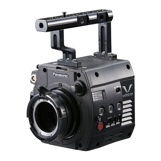
- Page 5 各部の名称 各部の名称 左面部 1 フランジバック調整穴 フランジバックを調整するときに使用します。 2 USER ボタン( 〈1〉/〈2〉/〈3〉 ) ユーザーが選択した機能をそれぞれのボタンに割り当てることができます。ボタンを押すことで、割 り当てられた機能が動作します。 3 メジャーフック / 焦点マーク〈 〉 MOS センサーの焦点位置を示します。 4 〈REC〉ボタン ボタンを押すと記録が始まります。再度押すと記録が停止します。記録中、ボタンが赤く点灯します。 5 〈SHUTTER〉スイッチ 電子シャッターの切り替えスイッチです。 6 〈EI〉スイッチ EXPOSURE INDEX(ゲイン)の切り替えスイッチです。 7 アクセサリー取り付け穴 アクセサリーを取り付けます。 f 取り付け穴サイズ - 3/8-16 UNC 8 ハンドル 9 〈LOCK〉スイッチ...
- Page 6 各部の名称 右面部 1 アクセサリー取り付け穴 アクセサリーを取り付けます。 f 取り付け穴サイズ - 3/8-16 UNC 2 ファン排気口 放熱用ファンの排気口です。使用中はふさがないでください。 3 レコーディングモジュールリリースレバー カメラモジュールからレコーディングモジュール(別売品)を取り外すレバーです。 4 アクセサリー取り付け穴 アクセサリーを取り付けます。 f 取り付け穴サイズ - 1/4-20 UNC(ねじ長さ 5.5 mm 以下) 5 USER ボタン( 〈4〉 ) ユーザーが選択した機能をこのボタンに割り当てることができます。ボタンを押すことで、割り当て られた機能が動作します。 6 メジャーフック MOS センサーの焦点位置を示します。被写体からの焦点距離を正確に測る場合は、このマークを基準 としてください。 7 〈VF〉端子...
- Page 7 各部の名称 前面部 1 アクセサリー取り付け穴 アクセサリーを取り付けます。 f 取り付け穴サイズ - 3/8-16 UNC(ねじ長さ 5.5 mm 以下) 2 レンズケーブル / マイクケーブルクランプ レンズケーブルやマイクケーブルを固定するためのクランプです。 3 レンズマウント レンズを取り付けます。 4 〈FILTER〉つまみ 被写体の照度に合わせてフィルターを選択します。 〈1〉 〈CLEAR〉 :ND フィルターを使用しません。 〈2〉 〈0.6ND〉 :MOS センサーに入る光の量を 1/4 にします。 〈3〉 〈1.2ND〉 :MOS センサーに入る光の量を 1/16 にします。 〈4〉...
- Page 8 各部の名称 後面部 1 ロックプレート レコーディングモジュールと接続するときに、固定する金具です。 2 レコーディングモジュール接続端子 レコーディングモジュールと接続する端子です。 上面部 1 ビューファインダー取り付け穴 ビューファインダーを取り付けます。 2 コントロールパネル取り付け金具取り付けビス穴 3 マイクホルダー取り付け位置 4 GPS モジュール位置 この部分に、GPS モジュールを内蔵しています。GPS 使用中は金属などでふさがないでください。 5 アクセサリー取り付け穴 アクセサリーを取り付けます。 f 取り付け穴サイズ - 1/4-20 UNC(ねじ長さ 5.5 mm 以下) - 3/8-16 UNC(ねじ長さ 5.5 mm 以下)...
- Page 9 各部の名称 下面部 1 ショルダーマウントモジュール / 三脚取り付け穴 ショルダーマウントモジュールや三脚を取り付けます。 f 取り付け穴サイズ - 1/4-20 UNC(ねじ長さ 5.5 mm 以下) - 3/8-16 UNC(ねじ長さ 5.5 mm 以下)...
- Page 10 モジュールの組み立て モジュールの組み立て カメラモジュールとレコーディングモジュールの組み立て 図 1 図 2 図 3 図 4 カメラモジュール後面上部のロックプレートにレコーディングモジュール前面上部のロックア ングルを合わせる。 (図 1) レコーディングモジュールをしっかり押し込み、カメラモジュールとレコーディングモジュー ルの接続端子を結合させる。 (図 2) NOTE t カメラモジュールの V エッジが下がっていると、 結合できません。 (図 3) カメラモジュールのレコーディ ングモジュールリリースレバーを、押し下げてください。V エッジが上がります。 (図 4) t V エッジ付近の機構部には、さわらないでください。V エッジが勢いよく動いて、けがをするおそれが あります。...
- Page 11 モジュールの組み立て HD カラービューファインダーの取り付け ロック 解除 図 2 図 1 スライダーユニットをカメラモジュール上面のビューファインダー取り付け穴に付属ねじ(2 本)で取り付ける。 (図 1) スライダーユニットに、ビューファインダー本体のプレートを上方よりスライドさせる。 (図 2) ビューファインダーのロックレバーは前方に倒して解除しておいてください。 ロックレバーを後方に倒して、ロックする。 付属の接続ケーブルを、ビューファインダーの接続端子とカメラモジュールの〈VF〉端子に接 続する。 コネクターの赤いマークを合わせて接続してください。...
- Page 12 モジュールの組み立て ショルダーマウントモジュールの取り付け カメラモジュールとレコーディングモジュールを取り付けてから行ってください。 スライドレール固定つまみ ストッパー ストッパー開口部 図 1 図 2 スライドレール固定つまみ ロック 解除 図 3 スライドレール固定つまみを解除する。 ストッパーを押しながら、スライドレールをショルダーマウントモジュールから外す。 (図 1) スライドレールのストッパー開口部をカメラ本体の前方向に向け、カメラ底面に付属のねじ(2 本)で図に示したねじ穴にしっかりと取り付ける。 (図 2) カメラ本体をショルダーマウントモジュールの溝に沿って後方からカチッと音がするまで前方 にスライドさせる。 (図 3) 取り付ける前にスライドレール固定つまみが、解除されているか確認してください。 カメラの重量バランスを考慮しスライド位置を調整した後、スライドレール固定つまみを時計 周りに回して固定する。 カメラが確実に固定されていることを確認してください。カメラのバランスが悪かったり、ねじの固 定がゆるかったりするとカメラが落下し、故障やけがの原因になります。...
- Page 13 保管について 保管について 保管上のお願い 湿気が少なく、比較的温度が一定な場所にそれぞれ保管してください。 r 本体 f ほこりが入らないように、柔らかい布で包んでください。...
- Page 14 f 保守・点検は機器の機能を常に良好な状態に維 書記載内容に基づき、無料修理させていただきま 持し、お客様が安心してご使用していただくた す。 めのものです。 f 部品の劣化、ごみ、ほこりの付着などにより突 保証期間:お買い上げ日から本体 1 年間 発的な故障、トラブルを未然に防ぐとともに、 安定した機能、性能の維持のために、定期的な 保守・点検を行ってください。 f 保守・点検(有料)についての詳しい内容は、 お買い上げの販売店にご相談ください。 修理を依頼されるとき 本書を再度ご確認のうえ、お買い上げの販売店までご連絡ください。 r 保証期間中の修理は. . . ご連絡いただきたい内容 保証書の記載内容に従って、修理させていただき 品名 カメラモジュール ます。詳しくは、保証書を参照してください。 品番 AU-V35C1G r 保証期間経過後の修理は. . . 製造番号 修理により、機能、性能の回復が可能な場合は、 お買い上げ日 ご希望により有料で修理させていただきます。 故障の状況...
- Page 15 定格 定格 定格の詳しい内容については、取扱いガイドをご覧ください。 総合 電源 DC 12 V(レコーディングモジュールより供給) 消費電力 31 W(本体のみ) は安全項目です。 動作周囲温度 0°C ~ 40°C 動作周囲湿度 10% ~ 85%(結露なし) 保存温度 −20°C ~ 60°C 質量 約 2.7 k ] 外形寸法(幅 × 高さ × 奥行) 165.0 mm×230.5 mm× 178.0 mm (突起部分および付属品を除く)...
- Page 16 ヨーロッパ連合以外の国の廃棄処分に関する情報 このシンボルマークは EU 域内でのみ有効です。 製品を廃棄する場合には、最寄りの市町村窓口、または販売店で、正しい廃棄方法を お問い合わせください。 ☎ © Panasonic Corporation 2014...
- Page 17 AU-V35C1G Model No. Before using this product, be sure to read “Read this first!” (pages 2 to 6). For more information, please visit the Panasonic website (http://pro-av.panasonic. ENGLISH net/en/manual/index.html), and refer to the Operating Guide. Bitte lesen Sie sorgfältig die „Bitte lesen Sie zuerst diesen Hinweis!“ vor der DEUTSCH Nutzung dieses Produkts.
-
Page 18: Read This First
Read this first! Read this first! indicates safety information. WARNING: CAUTION: f To reduce the risk of fire, do not expose Do not lift the unit by its handle while this equipment to rain or moisture. the tripod is attached. When the tripod is attached, its weight will also affect the f To reduce the risk of fire, keep this unit’s handle, possibly causing the handle... - Page 19 Read this first! indicates safety information. FCC NOTICE (USA) This device complies with part 15 of the FCC Rules. Operation is subject to the following two conditions: (1) This device may not cause harmful interference, and (2) this device must accept any interference received, including interference that may cause undesired operation.
- Page 20 Directive 1999/5/EC. Customers can download a copy of the original DoC for this product from our DoC server: http://www.doc.panasonic.de Contact in the EU: Panasonic Services Europe, a Division of Panasonic Marketing Europe GmbH, Panasonic Testing Centre, Winsbergring 15, 22525 Hamburg, F.R.Germany This product is intended to be used in the following countries.
- Page 21 El cliente puede descargar una copia de la DC original de este producto desde nuestro servidor DC: http://www.doc.panasonic.de Contacto en la U.E.: Panasonic Services Europe, a Division of Panasonic Marketing Europe GmbH, Panasonic Testing Centre, Winsbergring 15, 22525 Hamburg, F.R.Germany Este producto ha sido desarrollado para el uso en los siguientes países.
- Page 22 Read this first! EEE Yönetmeliğine Uygundur. EEE Complies with Directive of Turkey. Manufactured by: Panasonic Corporation, Osaka, Japan Importer’s name and address of pursuant to EU rules: Panasonic Marketing Europe GmbH Panasonic Testing Centre Winsbergring 15, 22525 Hamburg, Germany Декларація про Відповідність...
-
Page 23: Bitte Lesen Sie Zuerst Diesen Hinweis
Komponenten dieser Einheit für lange Zeit in direktem Hautkontakt stehen. Bei längerer Verwendung der Ausrüstung das Stativ einsetzen. Hergestellt von: Panasonic Corporation, Osaka, Japan Name und Adresse des Importeurs gemäß EU-Bestimmungen: Panasonic Marketing Europe GmbH Panasonic Testing Centre Winsbergring 15, 22525 Hamburg, Deutschland... -
Page 24: Lire Ces Informations En Premier
Quand vous utilisez l’appareil de façon prolongée, utilisez le trépied. NOTIFICATION (Canada) CAN ICES-3(B)/NMB-3(B) Fabriqué par : Panasonic Corporation, Osaka, Japon Nom et adresse de l’importateur en accord avec les règlements de l’Union Européenne : Panasonic Marketing Europe GmbH Panasonic Testing Centre... -
Page 25: Leggere Prima Quanto Segue
Quando si utilizza questo dispositivo per un periodo di tempo prolungato, fare uso del treppiede. Fabbricato da: Panasonic Corporation, Osaka, Giappone Nome e indirizzo dell’importatore in conformità con le normative UE: Panasonic Marketing Europe GmbH Panasonic Testing Centre... -
Page 26: Lea Esto Primero
Si va a utilizar el equipo durante largos periodos de tiempo, emplee el trípode. Fabricado por: Panasonic Corporation, Osaka, Japón Nombre y dirección del importador conforme a las normas de la UE: Panasonic Marketing Europe GmbH Panasonic Testing Centre... - Page 27 f All names, company names, product names, etc., contained in this document are trademarks or registered trademarks of their respective owners. How to read this document r Illustrations f Screenshots or illustrations may differ from the actual product. r Conventions used in this manual f Words and phrases in <...
-
Page 28: Table Of Contents
Contents Contents Read this first! Bitte lesen Sie zuerst diesen Hinweis! Lire ces informations en premier ! Leggere prima quanto segue! Lea esto primero Accessories Description of Parts Left side Right side Front Rear Bottom Assembling modules Assembling the camera module and recording module Mounting the Electronic HD color viewfinder Mounting the shoulder mount module Storing... -
Page 29: Description Of Parts
Description of Parts Description of Parts Left side 1 Lens flange back adjustment hole Used when adjusting the lens flange back. 2 USER buttons (<1>/<2>/<3>) User-selected functions can be assigned to each button. Pressing a button performs the assigned function. 3 Focus hook/focus mark <... -
Page 30: Right Side
Description of Parts Right side 1 Accessory mounting holes For attaching accessories. f Mounting hole size - 3/8-16 UNC 2 Fan outlet Fan outlet for dissipating heat. Do not block this when the camera is in use. 3 Recording module release lever Lever for removing the recording module (optional) from the camera module. -
Page 31: Front
Description of Parts Front 1 Accessory mounting holes For attaching accessories. f Mounting hole size - 3/8-16 UNC (screw length 5.5 mm or shorter) 2 Lens cable /microphone cable clamp Clamp for securing the lens and microphone cables. 3 Lens mount Holds the lens. -
Page 32: Rear
Description of Parts Rear 1 Lock plate Fitting which secures the recording module in place when connected. 2 Recording module connection terminal Terminal for connecting the recording module. 1 Viewfinder mounting holes For attaching the viewfinder. 2 Mounting hole for control panel mounting part 3 Microphone holder mounting position 4 GPS module position This part has a built-in GPS module. -
Page 33: Bottom
Description of Parts Bottom 1 Shoulder mount module/tripod mounting holes For attaching the shoulder mount module or a tripod. f Mounting hole size - 1/4-20 UNC (screw length 5.5 mm or shorter) - 3/8-16 UNC (screw length 5.5 mm or shorter) -
Page 34: Assembling Modules
Assembling modules Assembling modules Assembling the camera module and recording module Fig. 1 Fig. 2 Fig. 3 Fig. 4 Align the upper lock angle in front of the recording module with the upper lock plate at the rear of the camera module. (Fig. 1) Firmly push in the recording module and connect the connection terminals of the camera module and recording module. -
Page 35: Mounting The Electronic Hd Color Viewfinder
Assembling modules Mounting the Electronic HD color viewfinder Lock Release Fig. 2 Fig. 1 Attach the slider unit to the viewfinder mounting holes on top of the camera module using the two supplied screws. (Fig. 1) Slide the viewfinder plate from above into the slider unit. (Fig. 2) Release the viewfinder lock lever by pushing it forward. -
Page 36: Mounting The Shoulder Mount Module
Assembling modules Mounting the shoulder mount module Mount the shoulder mount module after mounting the camera module and recording module. Slide rail lock knob Stopper Stopper opening Fig. 1 Fig. 2 Slide rail lock knob Lock Release Fig. 3 Release the slide rail lock knob. Remove the slide rail from the shoulder mount module while pressing the stopper. - Page 37 Assembling modules After adjusting the slide position of the camera considering its weight balance, lock by turning the slide rail lock knob clockwise. Confirm that the camera is securely locked. The camera may fall causing a malfunction or injury when the camera is off balance or the screws are not locked securely.
-
Page 38: Storing
Storing Storing Cautions when storing the camera recorder Store the battery in a place where humidity is low and temperature is relatively constant. r Camera body f Wrap the camera recorder with a soft cloth so that dust does not get into it. -
Page 39: Specifications
Specifications Specifications For detailed specifications, refer to the Operating Guide. General Power DC 12 V (supplied by the recording module) Power consumption 31 W (body only) indicates safety information. Ambient operating temperature 0°C - 40°C (32°F - 104°F) Ambient operating humidity 10% - 85% (no condensation) Storage temperature −20°C - 60°C (−4°F - 140°F) - Page 40 Information on Disposal in other Countries outside the European Union This symbol is only valid in the European Union. If you wish to discard this product, please contact your local authorities or dealer and ask for the correct method of disposal. Web Site: http://panasonic.net © Panasonic Corporation 2014...
Need help?
Do you have a question about the AU-V35C1G and is the answer not in the manual?
Questions and answers