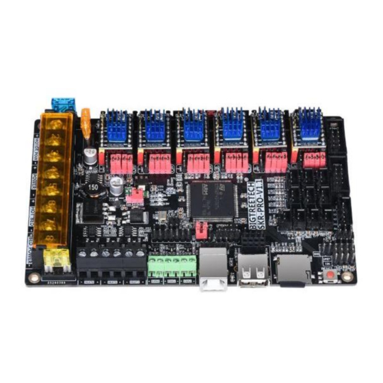
Summary of Contents for BIGTREETECH SKR PRO V1.1
- Page 1 SKR PRO V1.1 User Manual SHENZHEN BIGTREE TECHNOLOGY CO., LTD. BIGTREE-TECH.COM VERSION 1.1 AUTHOR: MERT CAPKIN...
-
Page 2: Product Introduction
BIGTREETECH MINI UPS V1.0 and a BIGTREETECH Relay V1.0 are needed. 8) The high performance heated bed MOSFET provides good heat dissipation. 9) Supported screens: BIGTREETECH 2.8 inch TFT and BIGTREETECH 3.5 inch TFT color touch screens, LCD2004 and LCD1286. These are just a few compatible screens, there are more options. -
Page 3: Board Specifications
Board specifications 1) Size: 147x95mm 2) Input voltage: 12V-24V DC 3) Installation size:138 * 86.5 mm 4) Max. heated bed power: 180W@12V, 360W@24V 5) Max. motor current: 15A 6) Max. accessories current: 10A Dimensions diagram 3 / 14... - Page 4 General wiring diagram Pin diagram 4 / 14...
-
Page 5: Power Wiring
Power wiring As shown above, three sets of power lines need to be connected to the board, namely, main power supply, motor power supply and heated bed power supply. The fourth connector on the board is for the heated bed output wires. When connecting, be sure to disconnect the mains voltage power supply and distinguish the positive and negative electrodes so as not to burn out the board. - Page 6 If you see the same as in the picture below, then the board is succesfully connected. Firmware You can find the needed firmware files on our Github page. BigTreeTech firmware: http://github.com/bigtreetech?tab=repositories Marlin2.0 firmware update method: After downloading the files, use Visual Studio Code to open the project for compilation.
- Page 7 Stepper driver and peripherals configuration 1) STEP/DIR mode Set the jumpers according to your microstepping settings. Note: the high level is connected to the above two row pins, and the low level is connected to the following two rows of pins 2) A4988 and DRV8825 driver If you want to use a A4988 or 8825 driver, it is necessary to short the two pins shown in the pink square with a jumper.
- Page 8 3) UART mode When using UART mode, you need to short the pins shown in the red square using a jumper. As shown in the figure below, the UART pin for TMC2208 is indicated by the red box. It is the 4 pin from the top.
- Page 9 5) SPI expansion port. The SPI expansion port shares its I/O pins with the SPI pins of the stepper motor drivers. It can only be used if you are not using a stepper motor driver in SPI mode. 6) USB host and USB flash drive selection As shown in the picture, when the jumper is connected to the left, the USB host function is turned on, and the USB flash drive function is turned off.
- Page 10 7) WIFI interface The WIFI interface is as shown in the picture below. When the WIFI modile is inserted, the edge of the board shown by the pink rectangle should face to the side of the board. See the pictures below. Note: To make use of WIFI function, a ESP8266 ESP-01S WIFI module is needed.
- Page 11 8) Stallguard pin As shown in the picture below, the pink squares indicate the pin corresponding to the stall detection. Take the TMC2209 as an example. When the stallguard function is not used, the stallguard pin of the TMC2209 needs to be removed by desoldering or cut off so that the mechanical switch can work normally.
- Page 12 9) Double Z-axis connection description ① Single Z connection ② Double Z-axis connection 10) Limit switch indicator light The LEDs next to the limit switch connectors show the status of the limit switches. Normally Closed When a normally closed limit switch is connected, the indicator light is off, and when it is triggered, the indicator LED turns on.
- Page 13 11) BL Touch 12) Automatic shutdown after print To make use of the automatic shutdown feature you need a BIGTREETECH Relay V1.0 module. See the user manual for the module for more information. You can find it here: https://github.com/bigtreetech 13 / 14...
- Page 14 13) Power failure detection To make use of the power failure detection feature you need a BIGTREETECH MINI UPS V1.0 module. See the user manual for the power failure module for more information. You can find it here: https://github.com/bigtreetech Notes 1) The firmware file name in the SD card cannot be changed, including capitalization.


Need help?
Do you have a question about the SKR PRO V1.1 and is the answer not in the manual?
Questions and answers