Table of Contents
Advertisement
Advertisement
Table of Contents

Subscribe to Our Youtube Channel
Related Manuals for BIGTREETECH OCTOPUS


Summary of Contents for BIGTREETECH OCTOPUS
- Page 1 BIGTREETECH OCTOPUS USER GUIDE May 12 2021 Version 01.00 Produced by BIGTREETECH...
-
Page 2: Table Of Contents
Produced by BIGTREETECH TABLE OF CONTENTS Table of Contents ........................1 Document Change History ......................2 Introduction to BIGTREETECH Octopus V1.0 ..............3 Octopus motherboard features ..................3 Octopus motherboard parameters ................. 5 Motherboard wiring......................7 Power wiring ........................7 Automatic power down wiring .................. -
Page 3: Document Change History
Produced by BIGTREETECH DOCUMENT CHANGE HISTORY VERSION CHANGES RELEASE DATE 01.00 Initial release 12/05/21 Page 2 of 25... -
Page 4: Introduction To Bigtreetech Octopus V1.0
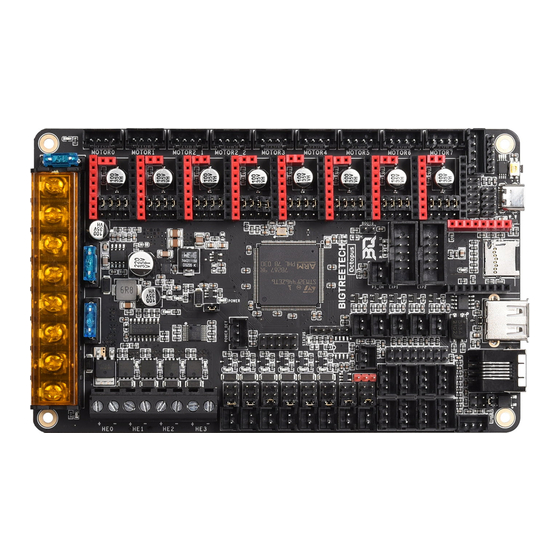
1 INTRODUCTION TO BIGTREETECH OCTOPUS V1.0 The BIGTREETECH Octopus V1.0 is a powerful and feature rich, 3D printer motherboard that supports up to 8 stepper drivers with 9 stepper driver outputs in total. It is designed and manufactured by the 3D printing team of Shenzhen Bigtree Technology Co.,Ltd 1.1 O... - Page 5 8. Includes USB-C interface which supports an emulated serial port that allows printing via USB. 9. Supports all versions of BIGTREETECH TFT screens and LCD12864 screens. 10. Supports multiple languages such as English and Simplified Chinese and can easily switch between different languages (when using the BTT TFT).
-
Page 6: Octopus Motherboard Parameters
Produced by BIGTREETECH in place on the board. The connector and passive circuitry are already provided. All that is required is the amplifier IC. 21. Thermistor input protection. This allows you to short a thermistor input directly to a voltage source (not that this makes it a good habit to pick up) up to Vin without causing damage to the motherboard. - Page 7 7. Temperature sensor interfaces: TB, T0, T1, T2, T3 (With direct inputs available that bypass the protection circuit for alternate use). 8. Display interfaces: BIGTREETECH TFT touch screen, LCD12864, LCD2004, etc. 9. PC communication interfaces: USB Type-C with configurable BAUD.
-
Page 8: Motherboard Wiring
Note: DO NOT alter the board wiring with the power on and be sure to get the polarity correct, otherwise you can cause damage to the motherboard. 2.2 A UTOMATIC POWER DOWN WIRING When using the BIGTREETECH Relay V1.2 module, the wiring can be performed as shown in the figure below. Page 7 of 25... -
Page 9: Bl Touch Wiring
Produced by BIGTREETECH Note: Since power will still be supplied to the Relay 1.2 module after it has cut power to the motherboard, it is extremely dangerous to touch the Relay 1.2 module while the printer is still connected to mains. Always remove all mains power when working on this wiring. -
Page 10: Power Loss Recovery Module Wiring
Produced by BIGTREETECH 2.4 P OWER LOSS RECOVERY MODULE WIRING When using the BIGTREETECH mini UPS, wire it to the motherboard as shown in the figure below. As always, never perform any work on the motherboard with power applied. 2.5 RGB LED... -
Page 11: Raspberry Pi Wiring
Produced by BIGTREETECH 2.6 R ASPBERRY PI WIRING Note: The 3.3V and GND pins for the SPI3 port were erroneously swapped on the silkscreen on the underside of some early boards. To be sure of the exact pinout please reference the PIN.pdf document for the SPI3 port. -
Page 12: Stepper Driver Operational Modes
Produced by BIGTREETECH 3 STEPPER DRIVER OPERATIONAL MODES Note: The octopus packs a ton of features which means there are many connectors and components. In order to keep the board size to a minimum we placed the stepper sockets close to each other. This means that drivers will have a snug fit. -
Page 13: Uart Mode
Produced by BIGTREETECH Note that if you are using drivers in step/dir mode that use a microstepping factor other than 16 then you cannot use any other drivers in SPI mode since the pins that are required to set the microstepping to anything other than 16 are also shared with SPI. -
Page 14: Motherboard Jumper Settings
4.1 F AN AND PROXIMITY SWITCH SETTINGS The Octopus features 6 PWM fan outputs and two “always on” fan outputs. There is also a dedicated pin header for a proximity sensor. These headers are shown in the image below. Note: The polarity of the fan ports was erroneously swapped on the silkscreen on the underside of some early boards. -
Page 15: Stallguard Jumper Settings
Produced by BIGTREETECH Configure the jumpers as below for 5V. Note: Since the jumpers carry a voltage rail directly from one of the regulators or from the input, if you short the jumpers in any way other than the shown connections, you will likely cause damage to the motherboard. -
Page 16: Mcu Power Jumper
Produced by BIGTREETECH 4.3 MCU POWER JUMPER The Octopus can be powered using the USB-C port by inserting the jumper as shown below. This can make it easier to compile and download firmware directly to the motherboard using DFU mode. -
Page 17: Motherboard Physical Specifications
Produced by BIGTREETECH 5 MOTHERBOARD PHYSICAL SPECIFICATIONS 5.1 M OTHERBOARD SIZE 5.2 M OTHERBOARD CONNECTORS 5.3 M OTHERBOARD PINS The image below is a snippet taken from the PINS.pdf document. For better viewability please consult the PINS.pdf document. Page 16 of 25... -
Page 18: Special Note On Expansion Interfaces
Expansion interfaces are provided for SPI, UART and I2C. In the very first production run of the Octopus the silkscreen on the underside of the PCB had two pins that were mislabeled on the SPI3 interface and two on the Raspberry Pi UART interface. -
Page 19: Communicating With The Motherboard
Produced by BIGTREETECH 6 COMMUNICATING WITH THE MOTHERBOARD After connecting the motherboard to a computer via a USB cable, the driver will be automatically installed (windows, linux and macos). Upon installation of the driver the motherboard should automatically enumerate as a virtual serial device which can be used for data transfer. -
Page 20: Motherboard Firmware Support
Produced by BIGTREETECH 7 MOTHERBOARD FIRMWARE SUPPORT You can find a pre-compiled version of Marlin for the Octopus by visiting https://github.com/bigtreetech?tab=repositories and looking for the Octopus repository. Alternately you can compile your own version using VScode. Covering how to compile... -
Page 21: Precautions
USB port) will overwrite the bootloader meaning that you will no longer have the option to update via SD card. 6. The stock Octopus does not come with a INA826AIDR amplifier chip. If you want to use the PT100 interface, you need to purchase a INA826AIDR chip (SOP-8 Package) separately and solder the chip into the correct position as shown below. - Page 22 With INA826AIDR BIGTREEETECH Octopus as shipped 7. The silkscreen on the first production run of the octopus had incorrectly labeled pins on the connectors listed below. To be sure that you are wiring on the correct pins please use the PINS.pdf document when using any of these connectors. The silkscreen has been corrected and all subsequent Octopus boards will reflect the correct mapping.
-
Page 23: Thank You From Bigtreetech
We appreciate your support and hope that you enjoy using your new Octopus motherboard. The BIGTREETECH team. Page 22 of 25... -
Page 24: Appendices
Note that the pin naming and ordering in the tables below is not consistent but the lowest number pin will always map to the pin named MS1 on the octopus and the numbering follows from there. - Page 25 Produced by BIGTREETECH Page 24 of 25...
Need help?
Do you have a question about the OCTOPUS and is the answer not in the manual?
Questions and answers