Table of Contents
Advertisement
Quick Links
See Warranty on page 20 for important information about commercial use of this product.
Operating Instructions and Parts Manual
Please read and save these instructions. Read carefully before attempting to assemble, install, operate or maintain the product described.
Protect yourself and others by observing all safety information. Failure to comply with instructions could result in personal injury and/or
property damage! Retain instructions for future reference.
Table of Contents
Description . . . . . . . . . . . . . . . . . . . . . .1
Unpacking . . . . . . . . . . . . . . . . . . . . . . .1
Safety Guidelines . . . . . . . . . . . . . . . . .1
Specifications. . . . . . . . . . . . . . . . . . . . .1
General Safety Information . . . . . . 2 - 4
Glossary of Terms . . . . . . . . . . . . . . . . .5
Pre-operation . . . . . . . . . . . . . . . . . 6 - 7
Operation . . . . . . . . . . . . . . . . . . . . 7 - 9
Maintenance . . . . . . . . . . . . . . . . . . . . .9
Storage . . . . . . . . . . . . . . . . . . . . . . . . .9
Welding Guidelines. . . . . . . . . . . 10 - 12
Troubleshooting Chart . . . . . . . . 13 - 14
General . . . . . . . . . . . . . . . . . . . . . .13
Generator . . . . . . . . . . . . . . . . . . . .13
Welder . . . . . . . . . . . . . . . . . . . . . .14
Welds . . . . . . . . . . . . . . . . . . . . . . .14
Wiring Diagram. . . . . . . . . . . . . . . . . .15
Welder / Generator Assembly. . . 16 - 17
Alternator Assembly . . . . . . . . . . 18 - 19
Warranty . . . . . . . . . . . . . . . . . . . . . . .20
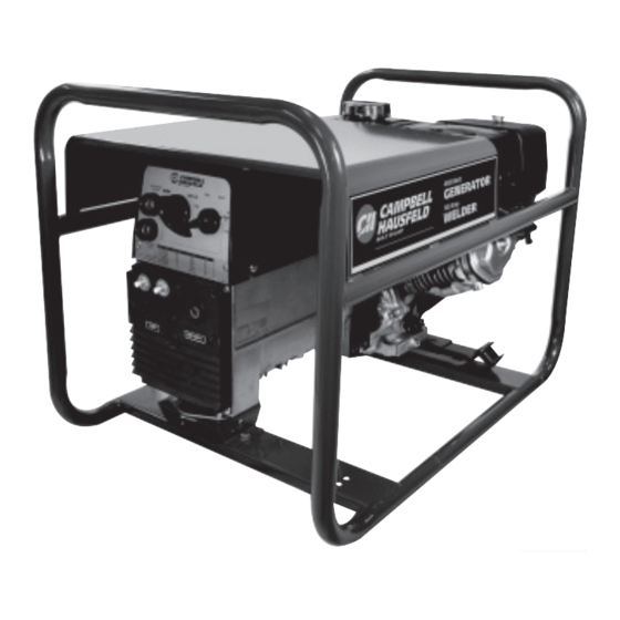
Description
This welder / generator is powered by
an air-cooled four cycle engine and
designed to run at maximum RPM and
give a continuous wattage as rated.
A low-oil level shutoff is provided to
protect the engine. The alternator is
thermostatically protected. To operate
this unit as a generator or welder,
set the switch on the front panel
accordingly.
© 2008 Campbell Hausfeld/Scott Fetzer
Unpacking
After unpacking the welder / generator,
inspect carefully for any damage that
may have occurred during transit. Make
sure to tighten fittings, bolts, etc.,
before putting unit into service. Report
any missing items by calling
1-800-543-6400.
Safety Guidelines
This manual contains information
that is very important to know and
understand. This information is
provided for SAFETY and to PREVENT
EQUIPMENT PROBLEMS. To help
recognize this information, observe the
following symbols.
hazardous situation which, if not
avoided, WILL result in death or serious
injury.
hazardous situation which, if not
avoided, COULD result in death or
serious injury.
hazardous situation which, if not
avoided, MAY result in minor or
moderate injury.
information, that if not followed, may
cause damage to equipment.
NOTE: Information that requires special
attention.
REMINDER: Keep your dated proof of purchase for warranty purposes!
Attach it to this manual or file it for safekeeping.
For parts, product & service information
visit www.chpower.com or call 1-800-543-6400
Welder /
Generator
Danger indicates an
imminently
Warning indicates a
potentially
Caution indicates a
potentially
Notice indicates
important
GW4500
Assistance?
Call Us First!
1-800-543-6400
Specifications
ENGINE
Engine Type . . . . . 270cc, 4 stroke OHV
Net Power . . . . . . . . . . . . . . . . . . . . 6.0
Ignition System . . Transistor Magneto
Start Mode . . . . . . . . . . . . . . . . Manual
Fuel Capacity . . . . . . . . . . . 1.4 gallons
Oil Capacity . . . . . . . 38.4 fluid ounces
GENERATOR
Type . . . . . . 2 pole, brushless rotating
Phase . . . . . . . . . . . . . . . . . . . . . Single
Continuous Power
Rating (KVA) . . . . . . . . . . . . . . . . . . 4.5
Rated Voltage (V) . . . . . . . . . 120 / 240
WELDER
Max Open Circuit Voltage (V). . . . 62.5
Rated Voltage (V) . . . . . . . . . . . . . 25.6
Rated Current (A) . . . . . . . . . . . . . .140
Max No Load Speed (r/min) . . . . .3850
Current Control Range (A) . . . 60 - 140
Rated Duty Cycle (%) . . . . . . . . . . . .35
Electrode Diameter (mm) . . . . 2.4 - 3.2
IN954000AV 8/08
Need
Advertisement
Table of Contents

Related Manuals for Campbell Hausfeld Welder / Generator GW4500


Summary of Contents for Campbell Hausfeld Welder / Generator GW4500
-
Page 1: Table Of Contents
REMINDER: Keep your dated proof of purchase for warranty purposes! © 2008 Campbell Hausfeld/Scott Fetzer Welder / Generator Unpacking After unpacking the welder / generator, inspect carefully for any damage that may have occurred during transit. -
Page 2: General Safety Information
Operating Instructions and Parts Manual General Safety Information CALIFORNIA PROPOSITION 65 The cables on this product may contain chemicals, including lead, known to the State of California to cause cancer and birth defects or other reproductive harm. Wash hands after handling. The engine exhaust from this product contains chemicals known to the State... - Page 3 General Safety Information (Continued) Always keep a fire extinguisher accessible while performing arc welding operations. • All installation, maintenance, repair and operation of this equipment should be performed by qualified persons only in accordance with national, state, and local codes. Improper use of electric arc welders can cause...
-
Page 4: General Safety Information
Operating Instructions and Parts Manual General Safety Information (Continued) Fire hazard! Do not weld on containers or pipes that contain or have contained flammable materials or gaseous or liquid combustibles. welding closed cylinders or containers such as tanks or drums can cause explosion if not properly vented! Verify that any cylinder or container to be welded has... -
Page 5: Glossary Of Terms
Getting To Know Your Welder / Generator Glossary of Terms AC or Alternating Current - electric current that reverses direction periodically. Sixty cycle current travels in both directions sixty times per second. Arc Length - the distance from the end of the electrode to the point where the arc makes contact with the work surface. -
Page 6: Pre-Operation
Operating Instructions and Parts Manual Pre-Operation LOCATION Selecting the proper location can significantly increase performance, reliability and life of the arc welder. • For best results locate the welder / generator in an environment that is clean and dry. Dust and dirt in the unit retain moisture and increase wear of moving parts. -
Page 7: Low Oil Shutdown
Pre-Operation (Continued) LOW OIL SHUTDOWN A low oil shutdown switch is provided to protect the engine and welder / generators on most extended run models. When engine oil level drops too low for proper engine operation, the low oil shutdown switch causes the engine to shut off. -
Page 8: Welder Operation
Operating Instructions and Parts Manual Generator Operation (Continued) INSTALLATION FOR STAND-BY USE Precautions must be taken to prevent electrical back feeding into utility systems. This requires isolation of the electrical system. To isolate the electrical system, perform the following procedures: Turn off the main electrical system switch prior to connecting the welder / generators. -
Page 9: Operation
Welder Operation (Continued) Tighten the set screw, securing the cable in place. Slide the insulated handle onto the electrode holder and tighten the phillips head screw. Do not overtighten the phillips head screw. Overtightening will damage the insulated handle. DINSE PLUGS (SEE FIGURE 3) Strip 1/2 inch of insulation from the opposite end of the welding cable. -
Page 10: Welding Guidelines
Operating Instructions and Parts Manual Welding Guidelines GENERAL This line of welding machines utilizes a process known as Shielded Metal-Arc Welding (SMAW). This process is used to bond metals by heating them with an electric arc created between the electrode and the work piece. Electrodes used for shielded metal arc welding have two parts. -
Page 11: Welding Guidelines
5º - 45º Travel Angle Work Angle Figure 6 - Weld Angle NOTE: Weld bead width (W) should be approximately twice the diameter for the electrode rod used. Normal Amps, Arc Length, Speed Amperage Too Low Amperage Too High Figure 7 - Weld Appearance Welding Guidelines (Continued) Work angle is the angle from... -
Page 12: Welding Positions
Operating Instructions and Parts Manual Welding Guidelines (Continued) SLAG REMOVAL Wear ANSI approved safety glasses (ANSI Standard Z87.1) and protective clothing when removing slag. Hot, flying debris can cause personal injury to anyone in the area. After completing the weld, wait for the welded sections to cool. - Page 13 Troubleshooting Chart - General Symptom Possible Cause(s) Engine will not start 1. Engine switch is set to "OFF". 2. Fuel valve is turned to "CLOSE". 3. Choke is open. 4. Engine is out of gas. 5. Engine is filled with contaminated or old gas 6.
-
Page 14: Troubleshooting Chart
Operating Instructions and Parts Manual Troubleshooting Chart - Welder Symptom Possible Cause(s) Welder runs but 1. Inadequate current at electrode does not weld 2. Poor connections at welder 3. Front panel switch set incorrectly 4. Open, shorted, or incorrect wiring 5. -
Page 15: Wiring Diagram
Figure 11 - Wiring Diagram - AC Welder / Generator Orange Yellow Brown White Grey Blue Black Violet Switch Power Generator/Welder Green White Yellow Black Brown Grey Blue Brown Blue White Green White Brown Charger Battery Orange www.chpower.com GW4500... -
Page 16: Welder / Generator Assembly
Operating Instructions and Parts Manual Welder / Generator Assembly Figure 12 www.chpower.com... -
Page 17: Replacement Parts List
Welding Cable - 6 AWG (6 foot) Warning Decal CPSC Warning Decal ▲ Standard hardware item, available at local hardware stores Address parts correspondence to: Campbell Hausfeld Attn: Parts Dept. 100 Production Drive Harrison, OH 45030 USA Part Number PM004264AV... -
Page 18: Alternator Assembly
Operating Instructions and Parts Manual Alternator Assembly Figure 13 www.chpower.com... - Page 19 Duplex Receptacle - 120V, 20A Nylock Nut - #8-32 Hex Head Screw - #8-32 x .75 inch ▲ Standard hardware item, available at local hardware stores Address parts correspondence to: Campbell Hausfeld Attn: Parts Dept. 100 Production Drive Harrison, OH 45030 USA Part Number...
-
Page 20: Warranty
A. Please call 800-543-6400 for warranty assistance. Provide dated proof of purchase and maintenance records. All welders must be delivered or shipped to the nearest Campbell Hausfeld Authorized Service Center. Freight costs, if any, must be borne by the purchaser.
Need help?
Do you have a question about the Welder / Generator GW4500 and is the answer not in the manual?
Questions and answers