Table of Contents

Related Manuals for PFT G 54 E


Summary of Contents for PFT G 54 E
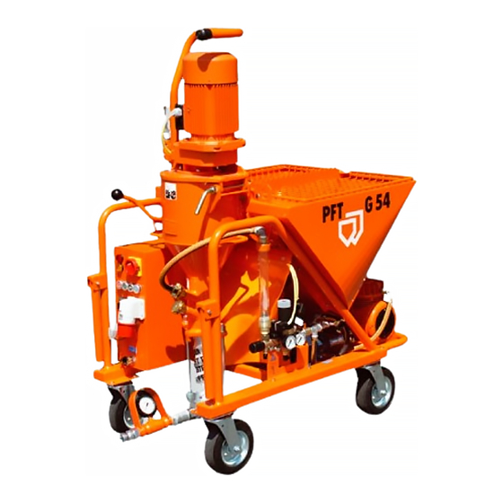
- Page 1 PFT G 54 E Operating Instructions 09/2006 OPERATING INSTRUCTIONS (Item number of the operating instructions: 00 08 31 50) (Item number of the machine – parts list: 00 05 69 13) MIXER PUMP PFT G 54 E WE KEEP THINGS MOVING...
- Page 2 It is prohibited to forward this document, even excerpts, without our written authorisation. All technical specifications, diagrams etc. are subject to copyright law. All rights, errors and modifications reserved. © by Knauf PFT GmbH & Co. KG Knauf PFT GmbH & Co.KG...
- Page 3 The PFT G 54 E mixer pump will be a reliable aid if it is operated properly and handled with care. Initial inspection after delivery An important task of all technicians delivering the PFT G 54 E mixer pump is the inspection of the machine settings at the end of the first work cycle.
-
Page 4: Table Of Contents
Basic safety instructions ....................................6 General instructions ...................................... 8 Overview of the G 54 E, item number: 00 05 69 13............................ 10 Overview of the control box, item number: 00 02 13 43 ..........................11 Overview of the water manifold, item number: 00 04 22 53 ........................12 Overview of the air manifold, item number: 00 04 22 62 .......................... -
Page 5: Intended Use
The PFT G 54 E is a continuously operating mixer pump for pre-mixed machinable mortar with a grain size of up to 3 mm. The PFT G 54 E can also be used to pump pasty materials. Observe all processing guidelines from the material manufacturer. -
Page 6: Basic Safety Instructions
PFT G 54 E Operating Instructions 09/2006 Basic safety instructions The following terms and symbols are used in these operating instructions for particularly important information: NOTE: Special information for running the machine efficiently WARNING! Special information, regulations and restrictions concerning the prevention of damage... - Page 7 PFT G 54 E Operating Instructions 09/2006 WARNING! The workplace of the user must be clean, tidy and free from objects which could restrict your freedom of movement. WARNING! The workplace must be illuminated appropriately for the intended work. Insufficient or excess illumination can be dangerous.
-
Page 8: General Instructions
PFT G 54 E Operating Instructions 09/2006 General instructions 1. The safety instructions and danger warnings on the machine must be observed and kept in a readable condition. 2. All procedures for switching the machine on and off and control indicators and signal lamps should be in compliance with the operating instructions. - Page 9 PFT G 54 E Operating Instructions 09/2006 24. Alterations to the machine are not permitted and result in Knauf PFT GmbH & Co. KG excluding any liability for claims. 25. The following safety instructions must also be observed for pumps and mixer pumps: Wear appropriate protective clothing during spraying work: safety goggles, safety shoes, safety clothing, gloves and, if necessary, protective skin cream and respirator masks.
-
Page 10: Overview Of The G 54 E, Item Number: 00 05 69 13
PFT G 54 E Operating Instructions 09/2006 Overview of the G 54 E, item number: 00 05 69 13 1. Motor connection cable 2. Mixer pump motor 3. Protection grille / material hopper 4. Material hopper 5. Tool box 6. High pressure pump 7. -
Page 11: Overview Of The Control Box, Item Number: 00 02 13 43
PFT G 54 E Operating Instructions 09/2006 Overview of the control box, item number: 00 02 13 43 1. Red “fault” control lamp 2. Orange “change direction of rotation” control lamp 3. Main reversing switch 4. Water pump socket, 16 A 5. -
Page 12: Overview Of The Water Manifold, Item Number: 00 04 22 53
PFT G 54 E Operating Instructions 09/2006 Overview of the water manifold, item number: 00 04 22 53 1. Water pressure gauge 2. Water safety switch 3. Pressure reducer 4. Solenoid valve 5. Outlet tap (antifreeze) 6. Needle valve (for regulating the water volume) 7. -
Page 13: Overview Of The Air Manifold, Item Number: 00 04 22 62
PFT G 54 E Operating Instructions 09/2006 Overview of the air manifold, item number: 00 04 22 62 1. Air from compressor 2. Counter flow valve 3. Compressor shutdown 4. Air pressure safety switch 5. Air to spraying gun Knauf PFT GmbH & Co.KG... -
Page 14: Checking The Setting Values (Factory Setting)
5.5 kW 11.5 A Direction of rotation The PFT G 54 mixer pump is equipped with a phase sequence relay that disables the machine if the direction of rotation is incorrect. The star wheel must be turned clockwise for right-hand rotation. - Page 15 A mortar pressure gauge must be used in compliance with the accident prevention regulations of the Builders’ Guild. Mortar pressure gauge The PFT mortar pressure gauge is used to monitor the mortar consistency quickly and easily. The mortar pressure gauge is part of the scope of delivery.
-
Page 16: Checking The Conveying Pressure And Backpressure
PFT G 54 E Operating Instructions 09/2006 Checking the conveying pressure and backpressure Checking the conveying pressure and backpressure: Connect a 10 m conveying hose. Connect a pressure tester with outlet tap to the end of the hose. Open the ball valve of the pressure tester. -
Page 17: Putting The Machine Into Service
PFT G 54 E Operating Instructions 09/2006 Putting the machine into service Transport the assemblies as closely as possible to the object to be processed (refer to Transport for the assembly). Lock the castor before putting the machine into service. -
Page 18: Adjust The Water Factor
PFT G 54 E Operating Instructions 09/2006 Connect the compressor. Connect the water pump. Connect the control box to the power supply. Turn on the main switch. Warning! The protective grille may not be removed while preparing or operating the machine. - Page 19 PFT G 54 E Operating Instructions 09/2006 Connect the water hose of the water flow meter to the upper water inlet of the mixing tube. Press the water flow button briefly. When starting the machine, there must be a sufficient amount of water in the mixing area so that the rotor head is covered (check for leaks, screw pump might be defective).
-
Page 20: Filling The Storage Container With Dry Mortar
PFT G 54 E Operating Instructions 09/2006 Filling the storage container with dry mortar Fill the storage container with dry mortar. Turn the star wheel switch (1) to automatic. Insert the blind plug (2). The machine is now ready for operation. The mortar consistency can now be checked at the mortar outlet flange (do not connect the mortar hose yet). -
Page 21: Spraying Gun
PFT G 54 E Operating Instructions 09/2006 Spraying gun Connect the spraying gun (finishing coat gun or crimp valve gun) to the mortar hose. Press the green “ON” pressure switch (1) and open the air tap on the spraying gun. -
Page 22: Mortar Consistency
PFT G 54 E Operating Instructions 09/2006 Mortar consistency The right mortar consistency is achieved once the material on the sprayed surface merges (we recommend applying material to wall surfaces from top to bottom). Even mixing and spraying cannot be ensured if the amount of water is insufficient, resulting in clogged hoses and the pumping components being subjected to greater wear. -
Page 23: Measures At The End Of Work And During Cleaning
PFT G 54 E Operating Instructions 09/2006 Measures at the end of work and during cleaning WARNING! Before removing the screw pump and opening the motor tilt flange, make absolutely sure the pump and hoses are depressurised. Observe the mortar pressure gauge display. - Page 24 PFT G 54 E Operating Instructions 09/2006 Then open the water valve until the sponge ball comes out of the end of the hose. For different hose diameters, the hoses should be cleaned separately with the appropriate sponge balls. Repeat this procedure if the hoses are very dirty.
-
Page 25: Clearing Hose Blockages
PFT G 54 E Operating Instructions 09/2006 Clearing hose blockages According to the accident prevention regulations of the Builders’ Guild, for safety reasons, all personnel assigned with unblocking hoses should wear safety goggles and position themselves in such a way as to avoid injury by discharged mortar. -
Page 26: Measures To Be Taken In The Event Of A Water Supply Failure
PFT G 54 E Operating Instructions 09/2006 Release the tie rod screws, remove the pump, push the rotor out of the stator and clean it thoroughly. Clean the pressure flange or agitator (ROTOMIX or ROTOQUIRL). Clean the mixing area and the mixing shaft with water and a spatula. - Page 27 PFT G 54 E Operating Instructions 09/2006 Switch on the compressor. Press the water flow button. The water is now blown out of the manifold with compressed air (at 1.5 bar for about 1 minute)! Empty the mixer pump by folding up the entire pump component.
-
Page 28: Maintenance
Transport First pull the main power cable and then undo all other power connections. Remove the water supply lines. The G 54 E consists of two units (mixing tube and material hopper), which can be transported separately. WARNING! Make sure all hoses are depressurised before opening the couplings (observe the mortar pressure gauge display). -
Page 29: Accessories
PFT delivery hood with electrical safety cabinet for G 54 E (item number 20 60 05 00) The PFT delivery hood is used to fill the PFT G 54 E mixer pump with dry material directly from the silo or container. If the material hopper is reported to be empty, the mixer pump is switched off by means of the remote control plug. -
Page 30: Fault - Cause - Remedy
PFT G 54 E Operating Instructions 09/2006 Fault – Cause - Remedy Fault Cause Remedy Machine will not start Water - Check water supply Water pressure too low - - Clean water inlet filters Gauge indicates less than 2.2 bar... - Page 31 PFT G 54 E Operating Instructions 09/2006 Machine will not stop - Air pressure safety switch misadjusted - Adjust air pressure safety switch or defective - Air hose or gaskets defective - Replace air hose or check compressor - Air tap on spraying gun defective...
-
Page 32: Spare Parts Drawing Of Material Hopper And Frame
PFT G 54 E Operating Instructions 09/2006 Spare parts drawing of material hopper and frame Knauf PFT GmbH & Co.KG... -
Page 33: Material Hopper And Frame Spare Parts List
00 00 13 40 Dust guard G 4 RAL 2004 20 10 10 10 Splint D 4.5 with ring 00 05 33 70 Material hopper G 54 E RAL 2004 20 20 63 14 Flat screw, M8 x 16, DIN 603, zinc-plated... -
Page 34: Star Wheel Spare Parts Drawing
PFT G 54 E Operating Instructions 09/2006 Star wheel spare parts drawing Knauf PFT GmbH & Co.KG... -
Page 35: Star Wheel Spare Parts List
PFT G 54 E Operating Instructions 09/2006 Star wheel spare parts list Pos. Item no. Description 00 07 27 90 Star wheel ring nut M24 galv. 00 04 91 79 Star wheel G 54, deep drawn, RAL 2004 20 10 18 10 Star wheel fixing plate 00 04 25 87 Gearbox, 0.75 kW, 28 U/min, ZFQ38 RAL 2004... -
Page 36: Gear Box Spare Parts Drawing
PFT G 54 E Operating Instructions 09/2006 Gear box spare parts drawing Knauf PFT GmbH & Co.KG... -
Page 37: Gearbox Spare Parts List
PFT G 54 E Operating Instructions 09/2006 Gearbox spare parts list Pos. Item no. Description 00 04 76 21 Tilt flange G 54 with tube bail RAL2004 00 04 67 94 Gearbox EFQ, 5.5 kW, 400 U, inclination switch, RAL2004 20 42 41 03 Motor connection cable, 1.9 m with CEE plug... -
Page 38: Mixing Tube Spare Parts Drawing
PFT G 54 E Operating Instructions 09/2006 Mixing tube spare parts drawing Knauf PFT GmbH & Co.KG... -
Page 39: Mixing Tube Spare Parts List
PFT G 54 E Operating Instructions 09/2006 Mixing tube spare parts list Pos. Item no. Description 20 10 06 50 Mixing shaft G 4/G 5 with exchangeable flange RAL 2004 20 10 09 00 Tilt flange gasket G 4, sponge rubber, 20 x 15 x 750 20 10 10 10 Splint D 4.5 with ring... -
Page 40: Control Box Spare Parts Drawing, Item Number: 00 02 13 43
PFT G 54 E Operating Instructions 09/2006 Control box spare parts drawing, item number: 00 02 13 43 Knauf PFT GmbH & Co.KG... -
Page 41: Control Box Spare Parts List, Item Number: 00 02 13 43
PFT G 54 E Operating Instructions 09/2006 Control box spare parts list, item number: 00 02 13 43 Pos. Item no. Description 00 03 52 00 Empty control box housing G 5 c RAL 2004 00 00 93 71 Motor protection switch 0-16 PKZM, 10-16 A 00 02 14 01 Auxiliary contact NHI-11-PKZO 00 00 93 70 Motor protection switch 1.6-2.5 A, PKZM 0-2.5... -
Page 42: Control Box Spare Parts Drawing, Item Number: 00 02 13 43
PFT G 54 E Operating Instructions 09/2006 Control box spare parts drawing, item number: 00 02 13 43 Knauf PFT GmbH & Co.KG... -
Page 43: Control Box Spare Parts List, Item Number: 00 02 13 43
PFT G 54 E Operating Instructions 09/2006 Control box spare parts list, item number: 00 02 13 43 Pos. Item no. Description 00 00 22 50 Control lamp, plug-type socket, yellow, without electric bulb, front installation 20 45 91 01 Light bulb, 42 V 2 W, plug-type socket, BA 9S... -
Page 44: Spare Parts Drawing Of Compressor (Item 20130015), Air Manifold (Item 00042262)
PFT G 54 E Operating Instructions 09/2006 Spare parts drawing of compressor (item 20130015), air manifold (item 00042262) Knauf PFT GmbH & Co.KG... -
Page 45: Spare Parts List For Compressor (Item 20130015), Air Manifold (Item 00042262)
PFT G 54 E Operating Instructions 09/2006 Spare parts list for compressor (item 20130015), air manifold (item 00042262) Pos. Item no. Description Compressor K2 N without automatic switch-off device, cpl. with 1.5 m cable 20 13 00 15 and plug, 4 x 16 A, unpacked, RAL 2004 20 20 20 00 EWO coupling, M component, 1/4"... -
Page 46: High Pressure Pump Spare Parts Drawing, Item Number: 00 05 67 92
PFT G 54 E Operating Instructions 09/2006 High pressure pump spare parts drawing, item number: 00 05 67 92 Knauf PFT GmbH & Co.KG... -
Page 47: High Pressure Pump Spare Parts List, Item Number: 00 05 67 92
Item no. Description 00 05 67 92 High pressure pump G 54 E 400 V Pk65, crosswise at bottom, cpl. 00 00 11 30 High pressure pump AV3 PK65N 20 20 54 00 Reduction nipple, 1" external thread, 1/2" internal thread, no. 241, zinc-plated 20 20 36 10 Curved section, 1/2"... -
Page 48: Water Manifold Spare Parts Drawing, Item Number: 00 04 22 53
PFT G 54 E Operating Instructions 09/2006 Water manifold spare parts drawing, item number: 00 04 22 53 Knauf PFT GmbH & Co.KG... -
Page 49: Water Manifold Spare Parts List, Item Number: 00 04 22 53
PFT G 54 E Operating Instructions 09/2006 Water manifold spare parts list, item number: 00 04 22 53 Pos. Item no. Description 20 20 17 00 Geka coupling gasket (pack of 50 pieces) 20 20 15 00 Geka coupling, 1/2" socket 20 20 25 00 Hose clip 20-23 20 21 36 12 Water/air hose, 1/2"... -
Page 50: Spraying Gun Spare Parts Drawing
PFT G 54 E Operating Instructions 09/2006 Spraying gun spare parts drawing Knauf PFT GmbH & Co.KG... -
Page 51: Spraying Gun Spare Parts List
PFT G 54 E Operating Instructions 09/2006 Spraying gun spare parts list 20 19 00 11 Spraying gun, 25 mm, LW24, nozzle 14 mm, 30° long 00 04 62 26 Spraying gun crimp valve, 25 mm, plastic 20 19 60 00 Spraying gun, 35 mm... -
Page 52: Main Power Circuit Diagram S1079
PFT G 54 E Operating Instructions 09/2006 Main power circuit diagram S1079 Knauf PFT GmbH & Co.KG... -
Page 53: Controlling Current Circuit Diagram S1079
PFT G 54 E Operating Instructions 09/2006 Controlling current circuit diagram S1079 Knauf PFT GmbH & Co.KG... -
Page 54: Check List For Annual Inspection By Specialist (Master Copy)
PFT G 54 E Operating Instructions 09/2006 Check list for annual inspection by specialist (master copy) This inspection must be carried out once a year by a specialist in accordance with ZH1/575. The machine and control box are awarded an inspection label as verification of this inspection. The inspection protocol is to be presented on demand. -
Page 55: Technical Specifications
PFT G 54 E Operating Instructions 09/2006 Technical specifications Machine designation G 54 E 00 05 69 13 Machine type Mixer pump Masonry mortar, reinforcing mortar, scratchwork, cement plaster, insulating plaster, screed mortar, filling compounds, Application of the machine reconstruction mortar, levelling compounds, liquid filler,... - Page 56 PFT G 54 E Operating Instructions 09/2006 WE KEEP THINGS MOVING Knauf PFT GmbH & Co. KG Postfach 60 97343 Iphofen Einersheimer Straße 53 97346 Iphofen Deutschland Telefon +49 9323 31-760 Telefax +49 9323 31-770 Technische Hotline +49 9323 31-1818 info@pft-iphofen.de...
Need help?
Do you have a question about the G 54 E and is the answer not in the manual?
Questions and answers