Table of Contents
Advertisement
Quick Links
1. Attach Scanners to pivot mount. Refer to separate document.
Before turning off power to the fixture, the fixture must not be rotating. This can be
accomplished with the Speed Control knob or HALT buttons located on the side panels.
This will allow the fixture to coast to a gentle stop. Otherwise, if A/C power is removed while
rotating, the fixture can stop suddenly and cause damage if the scanners are powered.
Shutdown procedure
1. Press the HALT button. The button should lock in place and the fixture will coast to a gentle
stop.
2. Adjust the Speed Control to the minimum setting. This is not necessary, but will ensure a
controlled start up condition.
3. Press the A/C power switch OFF, located on the side panel.
Startup procedure
1. Adjust the Speed Control to the minimum setting. This is not necessary, but will ensure a
controlled start up condition.
2. Press the A/C power switch ON, located on the side panel.
3. Release the HALT buttons by turning clockwise.
4. Adjust the Rotation Control to the desired setting +/- 0
5. Adjust the Speed Control to the desired setting.
Emergency procedure
1. Press one of the HALT buttons located on the left or right side panel. The button will lock in
place and the fixture will coast to a gentle stop.
2. Press the A/C power switch OFF located on the side panel.
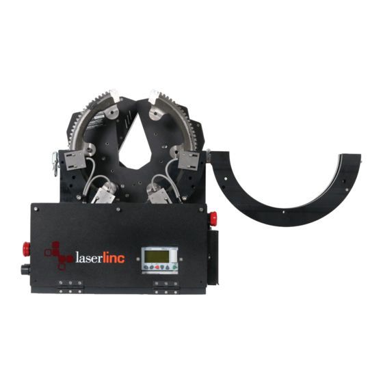
Pivot Table Quick Start Guide
IMPORTANT !!!
o
o
to +/- 90
Page 1 of 4
Advertisement
Table of Contents

Subscribe to Our Youtube Channel
Related Manuals for LaserLinc Pivot Table


Summary of Contents for LaserLinc Pivot Table
- Page 1 Pivot Table Quick Start Guide 1. Attach Scanners to pivot mount. Refer to separate document. IMPORTANT !!! Before turning off power to the fixture, the fixture must not be rotating. This can be accomplished with the Speed Control knob or HALT buttons located on the side panels.
- Page 2 Timeout Condition The fixture has a built-in watchdog timer that will force a Halt condition if a timer expires before seeing a limit sensor. During a timeout condition, the “Timeout” message will appear on the display and halt the fixture. If this occurs, then there is most likely a problem with a limit sensor(s) or magnet on the fixture.
- Page 3 PLC Front Panel Display The display has 4 lines text with the following information: Line 1: Status Displays the running status of the fixture Run–CW Fixture is running in a clockwise direction Run–CCW Fixture is running in a counter clockwise direction Coast Fixture is coasting (motor is temporarily not running) Halt...
- Page 4 ‘ESC’ Will force the PLC to reverse the direction of the fixture. This is not necessary for normal operations. Care must be taken to not force the fixture into an over limit rotation. ‘–’ Not functional ‘+’ Not functional ‘OK’ Not functional Controls HALT switch (located on the left and right side panels)
Need help?
Do you have a question about the Pivot Table and is the answer not in the manual?
Questions and answers