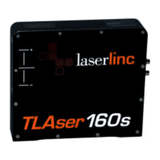
Summary of Contents for LaserLinc TLAser230
- Page 1 TLAserX30 / X60 / X120 Laser Scan Micrometers (130 / 160 / 1120 / 230 / 260 / 2120) Operator’s Manual April 2010 LaserLinc, Inc. 777 Zapata Drive Fairborn, Ohio 45324 Telephone: 937.318.2440 Fax: 937.318.2445...
- Page 2 LaserLinc, Inc. Disclaimer LaserLinc, Inc. has reviewed this manual thoroughly in order that it will be an easy to use guide to your TLAserX30/X60/X120 laser scan micrometer. All statements, technical information, and...
- Page 3 Mounting TLAser130 / 160 / 2120 ....................5 CABLING 130 / 160 / 1120 .......................6 Typical Connectors 130 / 160 / 1120 ...................6 TLASER230™ / 260™ / 2120™ LASER MICROMETER .............7 Specifications 230 / 260 / 2120....................7 Mounting TLAser230 / 260 / 2120 ....................7 CABLING 230 / 260 / 2120 .......................8...
- Page 4 Laser Micrometers – Theory of Operation Laser scan micrometers use a laser light source to measure diameter, gap, position, width, and other dimensions. The light source is focused onto the facets of a rotating mirror that reflects the laser beam into a collimating lens. The lens refracts the beam so that all paths of light from the mirror through the lens emerge parallel to each other.
- Page 5 LaserLinc, Inc. certifies compliance with U.S. safety regulations (21 CFR Chapter I, Subchapter J) on laser products, as stipulated by the U.S. Department of Health and Human Services. The LaserLinc, Inc. products shown here correspond to the category “CLASS II LASER PRODUCT”...
- Page 6 Specifications 130 / 160 / 1120 Mounting TLAser130 / 160 / 2120 Mounting Hole Drawings – • http://www.laserlinc.com/gauge_info/LaserLinc-TLAser130_mount.pdf http://public.laserlinc.com/info/160s/160s_mounting_dimensions.pdf http://public.laserlinc.com/info/1120s/1120s_Mounting_Dimensions.PDF Power is • Orientation - Any orientation is acceptable, as long as the mounting is secure and free from vibration.
- Page 7 Cabling 130 / 160 / 1120 Typical Connectors 130 / 160 / 1120 • Power and Data – both are keyed, and cannot be connected incorrectly. Connectors (plugs), if oriented correctly, will slide snugly into sockets. To remove, grasp metal plug housing and pull directly away from scanner. Plugs should slide out.
- Page 8 TLAser230™ / 260™ / 2120™ Laser Micrometer Getting Started • Be gentle with your scanner, it is a precision optical instrument. Rough treatment can reduce the precision, and the life expectancy of your scanner. Specifications 230 / 260 / 2120 Power is received from AC cord plugged into 110-220VAC 50-60 Hz, 2-phase electric.
- Page 9 Cabling 230 / 260 / 2120 Typical Connecters 230 / 260 / 2120 • Power and Data – both are keyed, and cannot be connected incorrectly. Connectors (plugs), if oriented correctly, will slide snugly into sockets. To remove, grasp metal plug housing and pull directly away from scanner. Plugs should slide out.
-
Page 10: Preventive Maintenance & Troubleshooting
Preventive Maintenance & Troubleshooting TLAserX30 / X60 / X120 Cleaning and Routine Maintenance • Cleaning – The windows of the TLAserX30/X60/X120 must always be clean to ensure the highest measurement accuracy. To clean the windows: 1. Remove the air purge or air purge if applicable. 2. - Page 11 2. The scanner data cable is not connected. Check that the scanner data cable is plugged into the scanner, and into the TLAser400 in the PC. • Problem: There are many problems that are not related to the scanner. • Possible Causes: 1. Please contact LaserLinc for further help.


Need help?
Do you have a question about the TLAser230 and is the answer not in the manual?
Questions and answers