Advertisement
Quick Links
OWNERS INSTRUCTION
MANUAL
102CM/40"
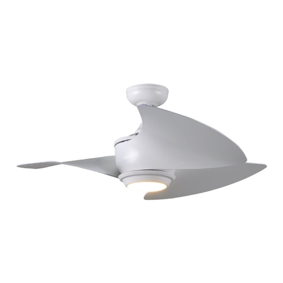
Cirrus
INSTALLATION
OPERATION
MAINTENANCE
CAUTION
READ INSTRUCTIONS CAREFULLY FOR SAFE
INSTALLATION AND FAN OPERATION. IF UNSURE CONSULT
A QUALIFIED ELECTRICIAN
SUITABLE FOR 230V/50 CYCLE ELECTRICAL SUPPLY
Enquiries on installing your fan please call our help line on
01959-564440
E-mail :
technical@fantasiaceilingfans.com
Advertisement

Subscribe to Our Youtube Channel
Related Manuals for Fantasia Elite Cirrus


Summary of Contents for Fantasia Elite Cirrus
- Page 1 OWNERS INSTRUCTION MANUAL 102CM/40” Cirrus INSTALLATION OPERATION MAINTENANCE CAUTION READ INSTRUCTIONS CAREFULLY FOR SAFE INSTALLATION AND FAN OPERATION. IF UNSURE CONSULT A QUALIFIED ELECTRICIAN SUITABLE FOR 230V/50 CYCLE ELECTRICAL SUPPLY Enquiries on installing your fan please call our help line on 01959-564440 E-mail : technical@fantasiaceilingfans.com...
-
Page 3: Important Notes
IMPORTANT NOTES : Please minimise risk of electrical shock by switching off electricity supply at the main circuit breaker. And read the following point carefully. To ensure the success of the installation be sure to read the instructions and study the diagrams thoroughly before commencing. -
Page 4: Part List
PART LIST Joist of Beam Hanger Bracket Round Steel Washer Spring Steel Washer Mounting Screw Drop Rod Canopy Canopy Screw Split Pin Cotter Pin Canopy Decorative Plate Boss Cover Blade Set Screw Fan Motor Light Plate Blade blade support plate Blade Set Screw Light Plate Screw Push Connector... - Page 5 Installing the fan All electrical work should only be undertaken after disconnection of the power by removing fuses or turning off the circuit breaker to ensure all pole isolation of the electrical supply. Your fan can be installed in a drop rod style of fan (Picture A). In this situation the drop rod assembly is used to lower the fan down from it’s mounting position slightly.
- Page 6 2. Drop rod assembly Remove the cotter pin and cross pin from the drop rod boss of the fan. If a longer drop rod (12” to 72” rod) is going to be used transfer the ball joint and the earth wire to the longer rod.
- Page 7 3. Remote Control and Wiring Instructions Warning: The power should have already been disconnected. Follow the steps below to connect the fan to your household wiring. Insert the receiver into the hanger bracket with the flat side of the receiver facing the ceiling. Put the receiver of remote control through hanger bracket (as picture).
- Page 8 Put all the wires carefully into canopy after finishing all the wires connection. Make sure connection are neatly tucked in the canopy. Slide the canopy up to the mounting bracket and place the key hole on the canopy over the loose canopy mounting screw on the mounting bracket.
- Page 9 4. Attaching the blades Remove the decorative cover from the fan motor housing by remove the two decorative cover screws on the motor housing. Remove three blade upper section attachment screws from the fan motor through the motor window. Secure fan upper section with the screw previously removed through the motor window.
- Page 10 5. Attaching the light plate and LED light fitter and glass The fan motor assembly is shipped with motor support plate to prevent movement during transportation. Remove the motor support plate . Remove one of the three light kit mounting plate screws from the mounting ring and loosen the other two screws.
- Page 11 6. Remote Control function and setup RECEIVER TRANSMITTER Set screw Remote pairing process: NOTE: This unit is equipped with an automatically learning type remote control. There are no frequency switches on the receiver and transmitter. The receiver unit will automatically scan the frequency from the hand-held remote.
-
Page 12: Product Disposal Instructions
Product Disposal Instructions This product has been classed as Electrical or Electronic Equipment and should not be disposed of with other household or commercial waste at the end of it’s working life. The Waste of Electrical and Electronic Equipment (WEEE) Directive (2002/96/EC) has been put in place to recycle products using best available precise and minimize the impact upon the environment. - Page 13 The ceiling fan itself, excluding accessories such as the Remote Control Transmitter and Receiver, is covered by a 10 year warranty. During this period, Fantasia Distribution Ltd will, at its discretion, repair or replace defective product. During this 10 years, the owner is responsible for labour costs incurred in removing and re-installing the fan, and for transport costs to Fantasia Distribution Ltd’s repair centre.
- Page 14 40”/102cm Cirrus FANTASIA DISTRIBUTION LTD. Unit B. The Flyers Way, Westerham, Kent, TN16 1DE Tel : (01959) 564 440 Fax : (01959) 564 829 E-MAIL: info@fantasiaceilingfans.com...
- Page 16 Please cut out this warranty page and send it in an envelope to the address below. Alternatively please go to our website www.fantasiaceilingfans.com and fill in the warranty section there. FANTASIA DISTRIBUTION LTD. Unit B. The Flyers Way, Westerham, Kent, TN16 1DE Tel : (01959) 564 440 Fax : (01959) 564 829 E-MAIL: info@fantasiaceilingfans.com...
Need help?
Do you have a question about the Elite Cirrus and is the answer not in the manual?
Questions and answers