
Related Manuals for Opsytec Dr. Grobel Radiometer RMD


Summary of Contents for Opsytec Dr. Grobel Radiometer RMD
- Page 1 Radiometer RMD Manual version 1.2.3E Opsytec Dr. Gröbel GmbH Am Hardtwald 6-8 D-76275 Ettlingen Telefon: +49(0)7243 / 9 47 83-50 Fax: +49(0)7243/ 9 47 83-65 info@opsytec.de...
-
Page 2: Table Of Contents
1Table of contents Table of contents Table of contents ....................... 2 Preface ..........................4 Directives and Norms ......................5 Identification ........................6 Manufacturer, Ordering of Spares and Customer Service ........6 Change history ......................6 Copyright ........................6 Device identification ....................6 Intended use ...................... - Page 3 1Table of contents Commissioning ......................23 Operation ..........................24 Switch on .........................25 Measuring with the RMD ..................25 8.2.1 Measurement screen ................25 8.2.2 Switching measuring modes ..............28 Menu ........................29 8.3.1 Settings.....................30 8.3.2 Change times ...................32 8.3.3 Information ....................32 8.3.4 Change language ..................33 Additional lamp factors* ...................34 Sensors with 2 channels: Erythem und NDT* ............34 8.5.1 Erythema sensor ..................35...
-
Page 4: Preface
2Preface Preface Dear Customer! Thank you for choosing a product manufactured by us! Please take your time to read this manual carefully. Please pay special attention to the safety instructions. This is the condition for safe handling and safe operation of the system and its components. If you have any questions that you do not find answered in this manual, please call us and we will be pleased to assist you. -
Page 5: Directives And Norms
3 Directives and Norms Directives and Norms The system is machinery under Annex II A of the Machinery Directive and is therefore delivered with a declaration of conformity and with a CE mark (in accordance with the Machinery Directive). Guidelines EC Directives 06/42/EC (Machinery) (partially observed) 2014/30/EC (EMC) -
Page 6: Identification
4 Identification Identification 4.1 Manufacturer, Ordering of Spares and Customer Service Opsytec Dr. Gröbel GmbH Am Hardtwald 6-8 D – 76275 Ettlingen Tel.: +49(0)7243 / 9 47 83-50 Fax: +49(0)7243 / 9 47 83-65 info@opsytec.de www.opsytec.com 4.2 Change history We reserve the right to make changes in content. Opsytec Dr. Gröbel GmbH is not liable for any errors in this documentation. -
Page 7: Intended Use
4 Identification 4.5 Intended use The RMD determines, with the corresponding sensors, the irradiance and dose in the UV and VIS spectral range and shows it on the integrated display. Operation is only allowed in dry environment. If required, the sensors are available splash-proof to IP65. When using the sensors, light, IR and UV radiation can be reflected and scattered. -
Page 8: Legal Information
4 Identification 4.7 Legal Information 4.7.1 Limitation of liability All information in this manual has been compiled taking into account the currently applicable standards and regulations, the technical standard and our many years of knowledge and experience. The manufacturer is not liable for damages in case that: •... - Page 9 4 Identification Improper use • Improper assembly, commissioning and operation • • Non-observance of the instructions in the manual regarding safety, transport, storage, assembly, commissioning, operation and maintenance Unauthorised spare parts have been used • • technical modifications have been made •...
-
Page 10: General
5 General General IMPORTANT SAFETY INSTRUCTIONS WARNING - Always observe the following basic precautions when using electrical equipment: a) Read all instructions before using the device. b)This device only used qualified trained personnel. See the training section of this manual. c) Do you know how to switch off the product become thoroughly familiar with the controls. -
Page 11: Information About The Symbols
5 General For a simple description, the above mentioned components are collectively referred to as system. 5.2 Information about the Symbols 5.2.1 SAFETY INSTRUCTIONS In this manual, safety information is indicated by means of symbols. Safety information is preceded by signal words that indicate the scope of risk. To avoid accidents and damage to persons or property, always follow the information and act prudently. -
Page 12: Prohibition Signs
5 General 5.2.2 Prohibition Signs General “Prohibited-sign” 5.2.3 WARNING SIGNS Warning of optical radiation (such as UV, IR, or visible radiation) Warning about electricity! 5.2.4 ATTENTION Wear eye protection! Opaque eye protection must be worn! Disconnect the power plug from the socket! Disconnect before carrying out maintenance or repair Use hand protection! Refer to the instruction manual/booklet... -
Page 13: Optional Functions
5 General 5.2.5 Optional functions Optional functions, not available for every system 5.3 Owner/operator information The System is used in the commercial sector. The owner/operator of the system is therefore subject to the legal obligations concerning work safety. In addition to the safety information in this manual, the generally applicable regulations valid for the application area of the system concerning safety, prevention of accidents and for protection of the environment must be noted and complied with. -
Page 14: Personnel Requirements
5 General 5.4 Personnel requirements The maximum number of qualified professionals who may be present at the site at the same time: 2 5.4.1 Qualifications WARNING Risk of injury when personnel are insufficiently qualified! If unqualified personnel carries out work on the system or stays in the danger area of the system risks arise that may cause severe injuries and serious material damage. -
Page 15: Personal Protective Equipment
5 General Instruction and training must be carried out in regular intervals by the owner/operator. For better tracking, execution of instruction and training should be recorded. 5.5 Personal protective equipment The purpose of personal protective equipment is to protect personnel from hazards that could affect their safety or health when working with the RMD and UV lamps, LEDs or lights. -
Page 16: Safety Instructions And Residual Risk
6 Safety instructions and residual risk Safety instructions and residual risk 6.1 General The system is state-of-the-art and has been built in compliance with recognized safety regulations. Nonetheless, its use may constitute risks for life and limb of the operating and repair personnel (service personnel) or third parties or impairments to the machine. -
Page 17: Safety Instructions In Relation To Normal Operation
6 Safety instructions and residual risk CAUTION Material damage due to high temperatures If the sensors are exposed to high temperatures, material damage may occur. This can lead to impairments or even to the inoperability of the sensors. -The sensors may be exposed to max. 60 °C. -If necessary, do not expose the sensors to radiation for long periods of time to avoid overheating. -
Page 18: Maintenance And Troubleshooting
6 Safety instructions and residual risk CAUTION Risk of damage Skin grease and dirt are absorbent in the UV and visible spectral • range. Avoid fingerprints on the optically active sensor surface. If • necessary, the components must be carefully cleaned with isopropanol. -
Page 19: Safety Instructions Regarding Service And Repair Work
6 Safety instructions and residual risk 6.4 Safety instructions regarding service and repair work CAUTION Risk of damage Skin grease and dirt are absorbent in the UV and visible spectral • range. • Avoid fingerprints on the optically active sensor surface. If necessary, the components must be carefully cleaned with isopropanol. -
Page 20: Safety Instructions Regarding The Power Supply
6 Safety instructions and residual risk 6.5 Safety instructions regarding the power supply The device is powered by lithium polymer batteries. To recharge the batteries, plug the cable into the port of the RMD and connect the other end to the supplied mains adapter. WARNING Fire hazard from lithium polymer batteries If the device is exposed to strong thermal or mechanical influences, the... -
Page 21: Description Of The System And Functional Overview
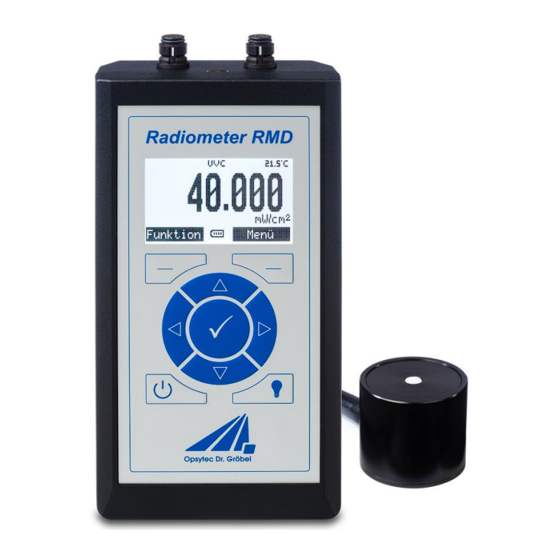
7 Description of the system and functional overview Description of the system and functional overview The RMD radiometer is a development of Opsytec Dr. Gröbel GmbH. More than 30 years of experience in all areas of irradiance and illuminance measurement have gone into this easy- to-use radiometer. - Page 22 7 Description of the system and functional overview But keep in mind that radiation measurements are not as easy as measuring lengths with a scale. Although the measuring device provides you with a number, this number depends in many ways on your measuring arrangement. For example, the measured value decreases with the cosine of the tilt angle when the sensor is tilted off the axis of the radiator-sensor.
-
Page 23: Transport, Storage, Delivery
7 Description of the system and functional overview 7.3 Transport, storage, delivery Sensitive components When transporting the system, therefore, make sure that it is not subjected to any load or hard impacts. Store the system according to the technical data - dry and dust-protected. Check the scope of delivery Check the delivered parts for completeness, damage or other conspicuous features. -
Page 24: Operation
8 Operation Operation The RMD radiometer is operated via nine keys. These are located on the front side below the display. The keys and the function assignment are shown below: Function Button Measuring mode Menu Main menu Functions Back Change mode ... -
Page 25: Switch On
8 Operation 8.1 Switch on The device is switched on with the on/off switch, or by plugging in a power connection. After the device has been started, the logo and the current firmware version appear on the display. After approx. 2 s the irradiance measurement appears, if no sensor is connected, a note appears. - Page 26 8 Operation Single measurement Irradiance Dual irradiance measurement If two identical sensors are connected, the channel number appears in the single measurement screen for differentiation. In the function menu of this measuring mode an offset can be set (chapter 8.2.2.1).
- Page 27 8 Operation 8.2.1.2 Dose measurement DOSE: 0.278 mW/cm² 2.780 mJ/cm² Menu Function Dual dose measurement Single dose measurement A dose measurement can be started, stopped and reset in the dose screen via the function menu. In the dual display, both sensors start the dose recording, in the single view only the one of the displayed sensor.
-
Page 28: Switching Measuring Modes
8 Operation 8.2.1.3 Switching measuring modes The measuring modes can be switched with the arrow keys up and down and the channels are switched left and right. On a sensor: Single measurement Dose On two sensors: ... -
Page 29: Menu
8 Operation The offset can be deleted or overwritten via the function menu. 8.3 Menu The main menu is opened in all measuring modes by pressing the right function key and includes the following points: back to irradiance Measurement • measurement General settings Chapter 8.3.1... -
Page 30: Settings
8 Operation 8.3.1 Settings The menu item Settings contains general settings for measurement and general settings for the handset. All settings must be confirmed with OK, otherwise they are not accepted! Averaging interval: period over which the average is calculated: none (0 s) no averaging •... - Page 31 8 Operation Backlight: The background light can be switched on and off at any time with the light button. Backlight is on • Backlight is off • Off after x min: Backlight goes off after x minutes • (see 8.3.2). Car.
-
Page 32: Change Times
8 Operation 8.3.2 Change times To change a timing in the menu, such as the time until the backlight is turned off, is described below: Switching off the background light should be changed from one minute to five minutes. Select Menu ->... -
Page 33: Change Language
8 Operation RMD: Display of information about the RMD Battery: Display of battery voltage, capacity, charge / discharge current and temperature. 8.3.4 Change language This menu item allows you to switch the system language between German and English. In the main menu the current language is displayed in brackets. -
Page 34: Additional Lamp Factors
8 Operation 8.4 Additional lamp factors* (This function is only available with a corresponding sensor with lamps factors) If a sensor is connected that has stored additional lamp factors there is an additional point in the function menu to switch the factors: To change a factors click Function ->... -
Page 35: Erythema Sensor
8 Operation 8.5.1 Erythema sensor In addition to the measured irradiances of the two channels, the erythema sensors also displayed the sum of these irradiances on the measurement screen. measurement screens dose, minimum and maximum measurements are analogous to the irradiance measurement screen. -
Page 36: Switch Off
8 Operation 8.6 Switch off Press and hold the button to switch off the unit. 8.7 Charging the battery The RMD can be charged via the supplied power supply. This should happen at the latest when the battery symbol starts flashing. Battery symbol: The battery is empty and should be charged urgently, symbol flashes... -
Page 37: Technical Data
9 Technical data Technical data The pin assignment for special versions may vary and can be found in the "Technical Drawing" appendix. General data Ambient temperature 0 to 60 °C Storage temperature, approx. -20 to +60 °C Air humidity 0% to 80% relative humidity, non-condensing Type of structure Handset Mounting position... - Page 38 9 Technical data TECHNICAL DATA SENSORS (TYPICALLY) Measuring range type plate The effective resolution and detection limit is type dependent and can be improved with longer averaging time. Resolution 0.001 µW/cm² Dose measuring range 0 - 100 MJ/cm² illuminance measurementsb. 0 - 500,000 lx Dynamic range up to 10...
- Page 39 9 Technical data...
-
Page 40: Errors / Faults
10 Errors / faults 10 Errors / faults The following notes and errormessages are directed to the user. The explanations should help to ensure proper operation. Possible reasons and remedies are given. Function / Display Meaning Measures The RMD cannot be switched on Battery empty Charge the battery. -
Page 41: Maintenance & Cleaning
11 Maintenance & Cleaning 11 Maintenance & Cleaning This chapter is intended for qualified users with maintenance tasks. The system is largely maintenance-free. Clean the optical components only if necessary. The RMD is a system that requires only occasional cleaning as maintenance according to need and calibration. -
Page 42: Calibration
11 Maintenance & Cleaning CAUTION The surfaces of the sensors can be affected by UV radiation heat it up. This can cause burns on contact. Therefore please note: - wear protective gloves if necessary - If necessary, observe the cooling phase CAUTION Risk of damage Skin grease and dirt are absorbent in the UV and visible spectral... - Page 43 11 Maintenance & Cleaning Open the software and click Next Accept license and continue Select the new firmware as TEXT file by browsing. If the device is in update mode and has been found, the update can be started with Upgrade Firmware. During the update, the USB connection must not be disconnected and the PC must not be switched off! The loading bar shows the progress of...
-
Page 44: Spare Parts
12 Spare parts 12 Spare parts Please contact us for replacement orders: Opsytec Dr. Gröbel GmbH At Hardtwald 6-8 76275 Ettlingen Germany Phone +49 - 7243 - 94 783 - 50 Fax +49 - 7243 - 94 783 - 65 Visit us on the Internet: www.opsytec.de When operating with damaged components or foreign components, no guarantee can be given for the correctness of the measured values. -
Page 45: Declaration Of Conformity
Company name: Opsytec Dr. Gröbel GmbH documentation: Road: Am Hardtwald 6-8 Place: 76275 Ettlingen Country: Germany product: Radiometer RMD with sensors Type designation: Type number: 814400 XXXX 8144XX XXXX The manufacturer hereby declares that we have developed, designed and produced the above-... -
Page 46: Notes
14 NOTES 14 NOTES CAUTION THIS MANUAL CONTAINS IMPORTANT SAFETY INSTRUCTIONS. KEEP THIS MANUAL.
Need help?
Do you have a question about the Radiometer RMD and is the answer not in the manual?
Questions and answers