
Subscribe to Our Youtube Channel
Related Manuals for Opsytec Dr. Grobel RM-32


Summary of Contents for Opsytec Dr. Grobel RM-32
- Page 1 Opsytec Dr. Gröbel GmbH Am Hardtwald 6-8 D-76275 Ettlingen Phone: +49(0)7243 / 9 47 83-50 Fax: +49(0)7243/ 9 47 83- 65info@opsytec.de Radiometer RM-32 Operating instructions Version: 1.4...
-
Page 2: Table Of Contents
1 Table of Contents 1 Table of Contents Table of contents ......................... 2 Change history ........................2 Symbol overview ......................... 2 Foreword ..........................3 General description ......................4 Settings and connections ..................... 5 Programming the panelmeter....................7 Integrated program routines ....................8 Communication RS232, RS485 or USB................ -
Page 3: Foreword
4 Foreword 4 Foreword Dear Customer, You have decided to purchase a high-quality precision UV measuring device. The operation is simple, please follow exactly our explanations in the enclosed operat- ing instructions, the measuring accuracy is then guaranteed. In order to guarantee this measurement accuracy over a longer period of use, we rec- ommend that you send your sensor to us for inspection every 12 months. -
Page 4: General Description
5 General description 5 General description The mains operated display unit RM-32 is designed for continuous monitoring of lamps mainly UV lamps. In addition to lamp monitoring, absorption, transmission and reflection measurements can also be carried out. The display is digital (3 1/2 digits) in W/m2. Two light-emitting diodes (SP1, SP2) indi- cate the status in relation to two preselectable thresholds. -
Page 5: Settings And Connections
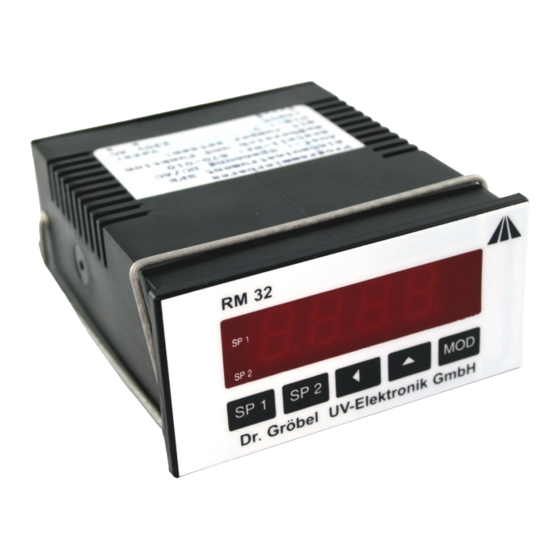
6 Settings and connections 6 Settings and connections 2.1 . Controls and display The indicator lights up when the RM-32 is connected to mains voltage. Fig. 1: Control element RM32 SP1: When the button is pressed, the SP1 pre-alarm setpoint is dis- played. - Page 6 6 Settings and connections 2.2 Terminal connection assignment Fig. 2: Terminal assignment of the terminals Relay SP2: potential-free switching output, alarm Relay SP1: potential-free switching output, pre-alarm PIN 9-11: RS232 output (optional via external board) Connect the circuit board with the sockets pointing downwards PIN 12: + 24 V, wire colour white PIN 13:...
-
Page 7: Programming The Panelmeter
The programmable panelmeter RM-32 can control numerous parameters of the measuring sequence with its integrated measuring routines. New values are set via the keyboard. This way, the desired measuring routine can be selected at the RM-32: Press MOD button Select routine with the arrow key ... -
Page 8: Integrated Program Routines
8 Integrated program routines 8 Integrated program routines Routine 1-5: not occupied Routine 6: Set decimal point The position of the decimal point on the LED display is set with 000: no decimal point (maximum display: 1999) 001: 1.000 002: 19.99 003: 199.9 dialed. - Page 9 8 Integrated program routines Routine 11: Switching point hysteresis SP1 Pre-alarm The hysteresis is set in W/m. Routine 12: Switching point hysteresis SP2 Alarm The hysteresis is set in W/m. Routine 15: Set relay function of SP1 pre-alarm Routine 16: Set relay function of SP2 alarm Each relay can act as a normally closed or normally open contact when the respective switching point is reached.
- Page 10 8 Integrated program routines Routine 20: Querying the minimum measured value The minimum value is continuously determined and stored since the last RESET. The reset is carried out when the min. or max. value is displayed by pressing the SP1 pre- alarm and SP2 alarm keys simultaneously for 3 seconds.
-
Page 11: Communication Rs232, Rs485 Or Usb
9 Communication RS232, RS485 or USB 9 Communication RS232, RS485 or USB Data transmission of the measured values of the SPE670 via serial interface. Routine 25: Activate/deactivate the serial interface Routine 27: Setting the baud rate of the serial interface Routine 34: Transmission cycles for the serial interface Jumper JP4 can be used to bypass the enable/disable by routine 25, the interface is then always active. - Page 12 9 Communication RS232, RS485 or USB Examples: Telegram = 21.05.2001 13:15 1.234Bar Characters ASCII decimal Example log with software hterm (not included):...
-
Page 13: Programming Rs232, Rs485 Or Usb
10 Programming RS232, RS485 or USB 10 Programming RS232, RS485 or USB The RM-32 contains a Real Time Clock for value output via the serial interface. The following routines are only used with the option RS 232 output. With the help of the routines, different parameters can be controlled. - Page 14 10 Programming RS232, RS485 or USB Routine 32: Real-Time Clock Date-Month This value is the month of the current date. Setting range: 1-12 Ex.1 = January, ... 12 = December Routine 33: Real-Time Clock Date-Year This value is the low-order part of the year of the current date. The high-order part is always kept at 20.
-
Page 15: Sub-D Rs232 Adapter
11 Sub-D RS232 adapter Routine 37: User-defined character of the measured value The user-defined character extends the display to three characters, which allows in- formation such as "Bar". The character does not appear in the display of the SPE670 but only in its printout. The character is entered as ASCII code decimal. For special characters (codes 128-256) the international code table from IBM (code page 437) is used. -
Page 16: Technical Data
12 Technical data 12 Technical data Dimensions DIN 43700: 96 x 48 mm Installation depth: approx. 115 mm Weight: 410 g Working temperature: -10 to +50° Celsius Storage temperature: -10 to +50° Celsius. switching threshold: programmable Switching hysteresis: programmable Relay data: 2 x 230 VAC / 5 A Mains supply: 230 V, 50-60 Hz, 3VA or 110 V, 50-60 Hz, 3VA,...
Need help?
Do you have a question about the RM-32 and is the answer not in the manual?
Questions and answers