
Related Manuals for Opsytec Dr. Grobel FlowMissio-C


Summary of Contents for Opsytec Dr. Grobel FlowMissio-C
- Page 1 UV-Photometer FlowMissio-C manual Version: 3.0 Opsytec Dr. Gröbel GmbH Goethestraße 17 76275 Ettlingen Tel.: 07243 94 783 50 Fax: 07243 94 783 65 info@uv-groebel.de...
-
Page 2: Table Of Contents
1 Change history Content Change history ......................2 Symbols Overview ....................3 General description ....................4 Important Notes ....................... 5 Installation ....................... 6 Operation ......................... 7 Settings ........................8 Calibration (formerly reference value) ............... 8 Threshold 1 and 2....................8 Hysteresis ...................... -
Page 3: Symbols Overview
2 Symbols Overview 2 Symbols Overview Meaning: Failure to observe the mentioned instructions can result in an injury of the user. Meaning: Failure to observe the mentioned instructions can result in a damage of the device. Meaning: Instructions are to be observed for the regular operation. -
Page 4: General Description
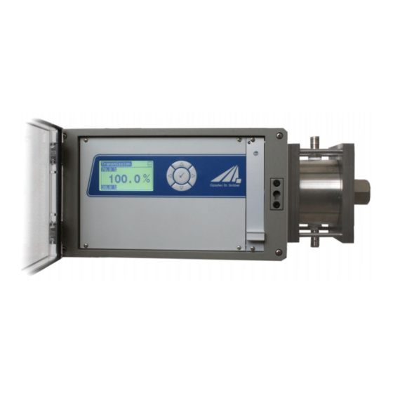
3 General description 3 General description The flow process photometer FlowMissio-C is a double-beam photometer for the con- trol of fresh and process water and other liquids at 254 nm. The photometer is out- standingly suitable for control of water quality in water plants or in production process- An internal sensor is measuring the power of the lamp and an external sensor the transmitted power of lamp. -
Page 5: Important Notes
4 Important Notes 4 Important Notes The operation manual is to be read completely prior to the startup and operation of the system. Before opening the system it has to be disconnected from the power supply and the absence of voltage is to be checked. The system is equipped with UV-C lamp. -
Page 6: Installation
5 Installation 5 Installation Please read the operating instructions carefully, before taking the equipment in action. Consider particularly the connection of the clamps (see chapter: Connections ). A wrong connection can lead to damages at the equipment Connect water inlet and water outlet. Then connect clamps and mains. -
Page 7: Operation
6 Operation 6 Operation After the first measurement the display shows the actual transmission: This value is directly determined using the two sensor signals. Use the cursor keys , to change screens. Screen 2, showing thresholds Screen 3, showing calculated transmission and extinction coefficients In screen 2 the threshold values are shown in lower left and upper left corner. -
Page 8: Settings
7 Settings 7 Settings To enter main menu press the key. Use the four cursor keys , , , and the center ok key () to navigate through the menu. Inverted text highlights the selected menu item. To confirm the selected function press the key. If you press the ... -
Page 9: Layer Thickness
8 Calculations 7.4 Layer thickness This submenu permits configuration of the layer thickness for transmittance calculation. A change of the layer thickness is possible from 1 mm to 999 mm in 1 mm steps. 7.5 Language Language can be set to English or German with key. 8 Calculations The UV photometer FlowMissio C is a two-ray photometer. -
Page 10: Maintenance And Service
9 Maintenance and service 9 Maintenance and service The UV photometer FlowMissio C does not require a lot of maintenance and care ser- vicing. The assigned UV lamp should be changed after 2000 operation hours (2 ½ months). 9.1 Exchange of the UV-lamp Switch-off the supply voltage for the photometer. - Page 11 9 Maintenance and service Put new desiccant into the housing. The function of the bags will remain longer, if you put more bags into the housing. Now close the housing again. Be sure the housing is closed and no cables are jammed. Also note that the transparent front cover should always be closed.
-
Page 12: Technical Data
10 Technical data 10 Technical data 10.1 Device Device number : 830701 Dimensions : approx. 400 x 250 x 340 Weight : 12.1 kg Operating temperature : 0 to 40 °C Housing : IP65 Signal output : 2 voltage free commutators 250V/1A Analog output : 4 - 20 mA, 20mA=110% Power supply... -
Page 13: Connections
10 Technical data 10.3 Connections NO theshold 1 (similar: alarm) NC theshold 1 (similar: alarm) Alarm NO theshold 2 (similar: Pre-alarm) NC theshold 2 (similar: Pre-alarm) Pre- alarm 4-20 mA High = 0-110% 4-20 mA Low RS232 1200Baud, 8 Data, 1 Stop, None Transmit Data (TxD –... -
Page 14: Spare Parts
10 Technical data 10.4 Spare parts Description Order number Lamp insert 93070101 Sealing set cuvette 93070102 Silica gel 93070103 UVCS Sensor 810312 Subject to changes... -
Page 15: Drawing
10 Technical data 10.5 drawing 220,0 241,0...
Need help?
Do you have a question about the FlowMissio-C and is the answer not in the manual?
Questions and answers