Table of Contents
Advertisement
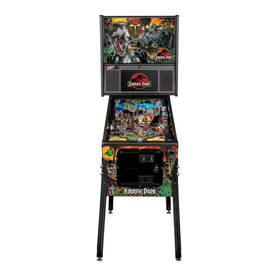
SETUP GUIDE
1-800-KICKERS - service@sternpinball.com
www.sternpinball.com - facebook.com/sternpinball
Stern Pinball machines are assembled in Elk Grove Village, Illinois,
USA; each pinball machine has unique characteristics that make it
a one-of-a-kind American-made product. Each machine will have
variations in appearance resulting from differences in the machine's
particular wood parts, digital art and mechanical assemblies. Stern
Pinball has inspected each game element to ensure it meets our quality
standards.
© Universal City Studios LLC and Amblin Entertainment, Inc. All Rights Reserved.
Advertisement
Table of Contents

Related Manuals for Stern Pinball JURASSIC PARK


Summary of Contents for Stern Pinball JURASSIC PARK
- Page 1 SETUP GUIDE 1-800-KICKERS - service@sternpinball.com www.sternpinball.com - facebook.com/sternpinball Stern Pinball machines are assembled in Elk Grove Village, Illinois, USA; each pinball machine has unique characteristics that make it a one-of-a-kind American-made product. Each machine will have variations in appearance resulting from differences in the machine’s particular wood parts, digital art and mechanical assemblies.
- Page 2 IMPORTANT SAFETY INSTRUCTIONS - PLEASE READ FIRST 1. Read these instructions. 2. Keep these instructions. 3. Heed all warnings. 4. Follow all instructions. 5. Do not operate this apparatus near water. 6. Clean only with a dry cloth. 7. Do not block any ventilation openings. Install in accordance with the manufacturer’s instructions. 8.
-
Page 3: Warranty
In no event shall the seller be liable for any anticipated profits, loss of profits, loss of use, accidental or consequential damages, or any other losses incurred by the customer in connection with the purchase of a Stern Pinball, Inc. part. -
Page 4: Warnings And Notices
IMPORTANT WARRANTY INFORMATION The electronics system, node network architecture, mechanical devices and associated software control systems in this pinball machine are designed to work with genuine Stern Pinball accessories and devices. Installation of non-authorized accessories, lamps, LED’s, motors or other devices or modification of electro-mechanical devices may damage the system and will void your warranty. -
Page 5: Parts List
PARTS LIST TOOLS REQUIRED: - 5/8” WRENCH OR SOCKET DRIVER BACKBOX FRONT MOLDING CABINET 1 GAME CABINET 4 LEGS AND LEVELERS 8 CABINET LEG BOLTS POWER CORD 2 BACKBOX BOLTS SETUP GUIDE 4 PINBALLS INDEX INITIAL SETUP • 6 VOLUME ADJUSTMENT • 11 SERVICE MENU •... - Page 6 INITIAL SETUP (2 PEOPLE REQUIRED) OPEN CARTON UNBOX GAME TAKE HOLD OF THE CABINET CAREFULLY TILT CARTON AND CAREFULLY PULL GAME FORWARD ONTO THE FLOOR OUT FROM CARTON REMOVE 4 LEGS STAND GAME ON FROM CARTON INSTALL BOTH FRONT LEGS CHECK THAT BOTTOM LEG EACH USING 2 OF THE BOLTS LEVELERS ARE FULLY SEATED...
- Page 7 WITH ASSISTANCE AGAIN, WITH ASSISTANCE, CAREFULLY LIFT THE BACK ROCK THE CABINET FORWARD OF THE CABINET AND PLACE ON A STURDY SUPPORT OBJECT UNTIL THE FRONT LEGS ARE INSTALL AND TIGHTEN BOTH ON THE FLOOR BACK LEGS USING 2 BOLTS EACH CUT THE STRAP LIFT BACKBOX...
- Page 8 SECURE BACKBOX USING THE TWO 5/8” BACKBOX BOLTS INCLUDED INSTALLING PINBALLS TO INSTALL PINBALLS SLIDE PLAYFIELD GLASS REACH INSIDE THE CABINET DOWN PARTIALLY AND PLACE AND LIFT THE TWO LATCHES THE PINBALLS INTO THE LOCATED ON EITHER SIDE OF PLAYFIELD AREA THE FRONT DOOR SLIDE PLAYFIELD GLASS SLIGHTLY TOWARDS THE...
-
Page 9: Tilt Adjustment
TILT ADJUSTMENT LEVELING ADJUST THE FRONT LOCATE THE TILT SENSOR INSIDE THE FRONT DOOR OR REAR LEVELERS AS BY THE LEFT SIDE PANEL. NECESSARY TO POSITION THE PLAYFIELD BUBBLE LEVEL, LOCATED ON THE REMOVE ANY SHIPPING FRONT RIGHT OF THE MATERIAL COVERING THE PLAYFIELD NEXT TO THE TILT SENSOR. - Page 10 PLAYFIELD ACCESS (FOR QUALIFIED SERVICE PERSONNEL ONLY) CAREFULLY LIFT THE PLAYFIELD BY THE UNSCREW THE BLACK MIDDLE OF THE PLASTIC ARCH PLAYFIELD KNOB AT THE BOTTOM CENTER OF THE PLAYFIELD PLASTIC ARCH LIFT THE PLAYFIELD UP AND THEN PULL SLIGHTLY TOWARDS YOU PLAYFIELD SHOULD STOP SLIDING AT A NOTCH ABOUT A...
-
Page 11: Volume Adjustment
VOLUME ADJUSTMENT Volume Menu Control: Green - Exit to Attract Mode Left Red - Decrease Volume Right Red - Increase Volume Black - Enter Service Menu Open the door on the front of the machine to gain access to the service control buttons. - Page 12 SERVICE MENU CONTINUED DIAGNOSTICS The Diagnostics Menu is used to access various tests to verify that your machine is working properly or to help diagnose potential problems. SWITCH Switch Test: Close each switch by hand and observe the display. If the switch is working properly it will display the name and corresponding number of the switch when it is actived.
- Page 13 SERVICE MENU CONTINUED GAME Bank: Tests the functionality of the 3-Bank Drop Target Assembly. Manually hit the drop targets and watch the display. The display should indicate any dropped targets. Useful for checking the functionality of switches in the drop target bank. If any of the targets are recessed, press the start button to reset them.
-
Page 14: Service Menu Adjustments
SERVICE MENU ADJUSTMENTS STANDARD ADJUSTMENTS ID Adjustment Name Default 53 Flipper Ball Launch Setting 55 Competition Mode No Target Time 21 Balls Per Game 22 Max Players Per Game 56 Fast Boot 23 Tilt Warnings 57 024 Option Coin Meter 59 Player Game Mode 24 Tilt Debounce 60 Player Competition Mode... -
Page 15: Driver Reference
NODE BOARD ID INSTRUCTION SHEET PLAYFIELD & CABINET ELECTRICAL PLAYFIELD FRONT PIN MODEL BACKBOX NODE 0 CN22 CPU NODE 0 NODE 8 Terminator Plug 045-5315-00 Node Bus Cable (RJ45) 604-5004-08-XX Serial Data Cable 036-8054-XX When replacing node boards, ensure DIP address switches are set correctly! PLAYFIELD REAR NODE REFERENCE... - Page 16 Driver Location Map...
-
Page 17: Switch Reference
SWITCH REFERENCE Name Node Node Conn. Input Input Ground Location Type Address Part Number Wire Wire Shooter Lane CN10 7/8/9 BLK Playfield Opto 8-SW-28 520-8115-00 tx Opto 520-8116-00 rx Left Outlane CN11 Playfield Rollover 8-SW-17 500-9935-03 Left Return CN11 Playfield Rollover 8-SW-18 500-9935-03 Lane Right Return... - Page 18 Switch Location Map...
- Page 19 SWITCH REFERENCE CONTINUED Name Node Node Conn. Input Input Ground Location Type Address Part Number Wire Wire 3-Bank Drop CN11 11/12 BLK Playfield Opto 8-SW-21 520-8497-00 Tgt Left 3-Bank Drop CN11 11/12 BLK Playfield Opto 8-SW-22 520-8497-00 Tgt Center 3-Bank Drop CN11 11/12 BLK Playfield...
- Page 20 SWITCH REFERENCE CONTINUED Name Node Node Conn. Input Input Ground Location Type Address Part Number Wire Wire C7 DIP 7 0-SW-6 Node C8 DIP 8 0-SW-7 Node C9 Service Select 0 CN25 Coin Door 0-SW-8 515-1963-00 C10 Service Plus CN25 Coin Door 0-SW-9 515-1963-00...
-
Page 21: Light Reference
LIGHT REFERENCE ID Name Node Node Conn. Ret. Ret. Src. Pin Src. Location Type Light Address Part Num- Ext. Wire Wire Color Left Outlane CN14 6 YEL Playfield Feature White 8-LP-3 520-5307-00 Left Return CN14 5 YEL Playfield Feature White 8-LP-4 520-5307-00 Lane Right Return... - Page 22 Light Location Map...
- Page 23 LIGHT REFERENCE CONTINUED ID Name Node Node Conn. Ret. Ret. Src. Pin Src. Location Type Light Address Part Num- Ext. Wire Wire Color 38 Super Jack- 1/2/3/4/5 RED Playfield Feature White 8-LP-32 520-5307-00 39 Smart Missle 8 1/2/3/4/5 RED Playfield Feature White 8-LP-36 520-5307-00 41 Spino Arrow 1/2/3/4 RED Playfield Feature White 8-LP-46 520-5307-00...
- Page 24 LIGHT REFERENCE CONTINUED ID Name Node Node Conn. Ret. Ret. Src. Pin Src. Location Type Light Address Part Num- Ext. Wire Wire Color 87 Backpanel GI CN15 7 Back- Flash White 8-LP-2 113-5045-08 (x3) panel 90 Top Pop 1/2/3/4/5 RED Playfield Flash White 8-LP-34 520-8059-00 Bumper 91 Bottom Pop...
-
Page 25: Motor Reference
MOTOR REFERENCE Name Node Node Conn. Ret. Ret. Src. Src. Location Type Light Address Part Number Ext. Wire Wire Color Motor A Playfield Motor - x-LP-0 520-6996-00 Enable Motor A Playfield Motor - x-LP-1 520-6996-00 Control 1A Motor A Playfield Motor - x-LP-2 520-6996-00... - Page 26 PLAYFIELD TOP ASSEMBLIES Part Number Description 500-2496-00 Shooter Assembly 515-5133-06-06 Flipper Bat 515-2443-00 Left Wireform Ramp 515-244-00 Right Wireform Ramp 535-2650-00 Gate 535-2631-00 Bracket 500-2592-00 Right Ramp 510-7846-00 Left Ramp 535-5307-03 Gate 535-5269-03 Bracket 511-5812-00 Right Rear Ramp 511-5033-00 Control Gate 545-5409-01 Reflector 550-5514-01...
- Page 28 PLAYFIELD BOTTOM ASSEMBLIES Part Number Description 500-1177-00 Auto Launch Assembly 500-9820-L8 Trough Assembly 500-6543-13-ND Left Flipper Assembly 500-6543-03-ND Right Flipper Assembly 500-9920-01 Left Slingshot 500-9920-01 Right Slingshot 535-0781-01 Playfield Support Rail 520-7011-00 LED Board 520-7017-72 Core Node Driver Board 500-7408-03 Drop Target Assembly 511-1981-01 Pop Bumper...
-
Page 30: Playfield Rubber Parts
PLAYFIELD RUBBER PARTS Qty Size (ID) Size (OD) Durometer Color Part Number 3/16" Black 545-5348-01 5/16" Black 545-5348-02 3/4" Black 545-5348-04 1" Black 545-5348-05 1-1/4" Black 545-5348-06 1-1/2" Black 545-5348-07 1-3/4" Black 545-5348-21 2-1/2" Black 545-5348-09 7/16" Black 545-5348-17 Qty Description Color Part Number Flipper Rubber... - Page 32 1-800-KICKERS JURASSIC PARK #500-55M4-01 MANUAL #780-50M4-00 PARTS.SERVICE@STERNPINBALL.COM WWW.STERNPINBALL.COM *780-50M4-00* FACEBOOK.COM/STERNPINBALL...
Need help?
Do you have a question about the JURASSIC PARK and is the answer not in the manual?
Questions and answers