Table of Contents
Advertisement
Advertisement
Table of Contents

Related Manuals for Key-Disp KD716


Summary of Contents for Key-Disp KD716
-
Page 2: Table Of Contents
Contents Product name and model................................. 1 Specifications..................................... 1 Appearance and dimension..............................1 Function summary and distribution............................2 ◆Function summary................................3 ◆Function distribution................................3 General operations..................................3 ◆Switch E-bike system ON/OFF............................4 ◆Display interface.................................4 ◆Switch push assist mode ON/OFF..........................4 ◆Switch lighting ON/OFF..............................5 ◆Power assist level................................ - Page 3 Recover default settings.................................18 Quality assurance and warranty scope..........................19 Wire connection layout................................19 Warnings....................................19 Attached list 1:error code definitions..........................20 Attached list 2:PAS ratio default value table........................20...
-
Page 4: Product Name And Model
Product model E-bike Intelligent LCD display Model: KD716 Specifications ● 24V/36V/48V Power Supply ● Rated working current: 10mA ● The maximum working current: 30mA ● Off-state leakage current: <1μA ● Operating temperature: -20℃~ 60℃ ● Storage temperature: -30℃~ 70℃ Size... -
Page 5: Function Summary And Distribution
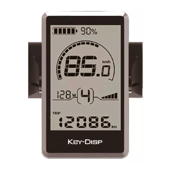
Remote appearance and dimensional drawing (unit: mm) Function summary and distribution ◆Function summary KD716 display has many functions to meet your cycling needs. The indication factors are as follows: ●Intelligent battery power indication ●Motor power ●Assist level ●Speed indication (incl. current speed, Max. speed and Ave. speed) -
Page 6: Function Distribution
●Recover default settings ◆Function distribution KD716 Function distribution interface General operations: ◆Switching the E-bike System On/Off Press remote power button to switch on the E-bike system and provide the power supply for the controller. -
Page 7: Switch E-Bike System On/Off
◆Display Interface After switching on the E-bike system, the display will show current Speed and Trip Distance by default. Press remote “i” button will show more riding data below: Trip Distance (Km) →ODO (Km) →Max. Speed (Km/h) → Ave. Speed (Km/h) →Trip Time (Min.). Display interface ◆Switching Push-assist Mode On/Off To activate the push-assist function, press and hold the “-”... -
Page 8: Switch Lighting On/Off
◆Switching Lighting On/Off To switch on the display backlight and headlight of E-bike, hold the UP button for 2s. When you ride the bike at night or in a place where there’s a lack of light, you can turn on LCD backlight. Likewise hold the UP button for 2s again, display backlight and E-bike headlight will be switched off. -
Page 9: Battery Indicator
◆Battery Power Indicator The five battery power bars represent the capacity of the battery. The five battery bars are bright when the battery is in full voltage. When the battery is in low voltage, battery frame will flash at the frequency of 1HZ to give a notice that the battery needs to be recharged immediately Flash (low voltage) Battery indicator interface... -
Page 10: Error Code Indication
◆Error code indication When a fault occurs in E-bike electronic control system, the corresponding error code will be shown on the display. The definitions of the codes are listed in Attached list 1. Error code interface ■Make the display repaired when an error code appears. Or else you will not be able to ride E-bike normally. -
Page 11: Backlight Brightness
Trip distance clearance interface ◆Backlight settings: bL represents backlight settings. Level “1” is the lowest brightness. Level “2” is the medium brightness. Level “3” is the highest brightness. The default value is “1”. To change the backlight brightness, press the UP/DOWN button to increase or decrease until the desired brightness level is displayed. -
Page 12: Unit Conversion Km/Miles
◆Unit conversion KM/Miles U represents unit settings, “1” is mile and “2” is kilometer. The default value is “2”. To convert unit, press the UP/DOWN button to increase or decrease until the desired unit is displayed. Press the i button to store a changed setting and then access trip distance clearance settings again or long press the i button for 2s and exit general settings Miles and KM conversion interface. -
Page 13: Speed Limit
Wheel diameter settings interface ◆Speed limit Settings LS represents the speed limit settings. When the current speed is more than speed limit, the E-bike system will be switched off automatically. Speed limit ranges from 12Km/h to 40Km/h. The default value is 25Km/h. Press the UP/DOWN button to increase or decrease the speed limit values until the desired one is displayed. -
Page 14: Personalized Parameters Settings
Personalized Parameter Settings Personalized Parameter Settings can meet a variety of requirements. 8 settings are Battery Power Bar Settings, Power assist level Settings, Over-current Cut Settings, Power Assist Sensor Settings, Speed Sensor Settings, Throttle Function Settings, System Settings and Power-on Password Settings. Hold UP and DOWN button simultaneously for 2 seconds to enter general settings and Hold UP and DOWN button simultaneously for another 2 seconds to enter personalized parameter settings interface. -
Page 15: Power Assist Level Settings(Optional)
Power Assist Level Settings (optional) ◆ Power Assist Level options There are 8 PAS level modes for power assist settings: 0-3, 1-3, 0-5, 1-5, 0-7, 1-7, 0-9, 1-9. The default mode is 0-5. Press the UP/DOWN button to increase or decrease until the desired mode is displayed. Press i button to confirm and access the corresponding PAS ratio settings page. -
Page 16: Controller Over-Current Cut Settings(Optional)
◆Controller Over-Current Cut Settings (optional) CUR represents controller over-current cut settings. CUR value ranges from 7.0A to 22.0A. The default value is 15A. Press the UP/DOWN button to increase or decrease the value of the current. Hold i button for 2s to confirm and then return to previous menu. Current settings interface ◆PAS sensor settings(optional)... -
Page 17: Power Assist Magnet Number Settings
Magnet Quantity Settings n represents magnet numbers of PAS disk. The default value is 6. Press the UP/DOWN button to choose quantity for changing magnet numbers of PAS disk, Hold i button for 2s to confirm and then return to previous menu. PAS magnet disks settings ◆Speed sensor settings (optional) SPS represents speed sensor settings. -
Page 18: System Settings(Optional
Throttle level enable/disable HF-y means throttle speed is limited by current PAS level while HF-n means throttle speed is not limited by current PAS level. The default value is n. If you choose y, the maximum speed can only be the highest speed powered by current PAS level when you twist the throttle. -
Page 19: Push Assist Button Enable/Disable
Push-assist button enable/disable settings PUS means push-assist button enable/disable settings. Press UP/DOWN button to choose Y or N. Y is enable while N is disable. Press i to confirm. The default value is Y. Push-assist button enable/disable Slow Start up Settings SSP represents slow start up. -
Page 20: Power-On Password Enable/Disable
Power-on password input interface Power-on Password Enable/Disable Press UP or DOWN button to choose Y or N and press i button to confirm. If it is Y, press i button and then access power-on password change interface; otherwise exit the power-on password settings interface and return to previous menu. -
Page 21: Exit Settings
one by one until the new 4-digit password is completed. To store the new power-on password, hold i button for 2 s and then exit settings. When you switch the E-bike system on next time, the display will show P1, 0000, please input the new password to power on. -
Page 22: Quality Assurance And Warranty Scope
Quality assurance and warranty scope: I. Warranty: 1) The warranty will be valid only for products used in normal usage and conditions. 2) The warranty is valid for 24 months after the shipment or delivery to the customer. II. The following cases do not belong to warranty scope: 1) The display is demolished. -
Page 23: Attached List 1:Error Code Definitions
Attached list 1:Error code definition Error Code Definition Current Abnormality Throttle Abnormality Motor Phase Abnormality Motor Hall Signal Abnormality Brake Abnormality Communication Abnormality Attached list 2: PAS ratio default value table Level Level mode 0-3/1-3 — — — — — —...
Need help?
Do you have a question about the KD716 and is the answer not in the manual?
Questions and answers