Table of Contents
Advertisement
Quick Links
Advertisement
Table of Contents

Related Manuals for Key-Disp KD78C


Summary of Contents for Key-Disp KD78C
-
Page 2: Table Of Contents
Contents Product name and model................................1 Specifications....................................1 Appearance and dimension................................1 Function and button definition..............................2 ◆Function summary................................... 2 ◆Button definition..................................2 General operations..................................3 ◆Switch the E-bike system ON/OFF..............................3 ◆Display interface..................................3 ◆Switch push-assistance mode ON/OFF............................3 ◆Switch lighting ON/OFF................................4 ◆Assist level selection................................4 ◆Battery level indicator..................................4 ◆Error code indication................................5 General Settings..................................6 ◆Trip distance clearance................................6... - Page 3 Warnings.....................................18...
-
Page 4: Product Name And Model
Product name and model E-bike Intelligent LCD display Model: KD78C Specifications ● 2.0” segment LCD ● 36V/48V/52V Power Supply ● Rated working current: 10mA ● The maximum working current: 30mA ● Communication: Uart/CAN ● Operating temperature: -10℃~ 40℃ ● Storage temperature: -20℃~ 60℃... -
Page 5: Function And Button Definition
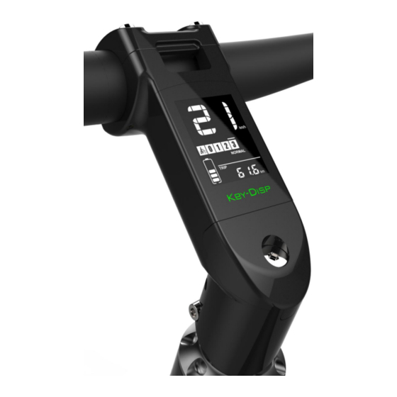
Function and button definition ◆Function summary KD78C display has many functions to meet riders’ cycling needs. The indication elements are as follows: ●Intelligent Battery SOC ●Motor power indicator ●Assist level indicator and adjustments ●Speed indication (incl. current speed, Max. speed and Avg. speed) ●ODO and Trip... -
Page 6: General Operations
General operations: ◆Switching the E-bike System On/Off When battery power is on, the display switches on automatically. when battery power goes out, the display switches off automatically. When E-bike system is switched off, display does not use the battery power any more. the leakage current is less than 1 μA. -
Page 7: Switch Lighting On/Off
◆Switching Lighting On/Off Hold + for 2 seconds, display backlight dims and bike headlight is on and headlight icon comes out. Hold + button for 2 seconds again to switch off the headlight and light icon is gone and display backlight brightness recovers. -
Page 8: Error Code Indication
◆Motor Power Indicator The watts value of the motor can be read via interface below by digits. Motor power interface ◆Error code indication The components of the E-bike system are continuously and automatically monitored. When an error is detected, the error code comes out and malfunction icon shows. The whole interface is code plus error indication icon. -
Page 9: General Settings
General Settings At the normal display interface, hold both ‘+’ and ‘-’ simultaneously for 2 seconds to enter General Settings. ▉All the Settings are done to a parked E-bike. Please refer to attached list 2 for the symbol definition. ◆Trip Distance Clearance TC represents trip distance clearance setting. -
Page 10: Toggle The Unit Km/Miles
◆Toggle the unit KM/Mile U represents unit settings, “1” is mile and “2” is kilometer. The default value is “2”. To toggle the unit, press the +/- button to switch between KM/Mile for the speed and mileage. Press the i button to store a changed setting and then access trip distance clearance setting again or hold the i button for 2s and exit General Settings. -
Page 11: Personalized Parameters Settings
Personalized Parameter Settings Personalized Parameter Settings can meet a variety of requirements. 8 settings are Battery Power Bar Settings, Power Assist Level Settings, Over-current Cut Settings, Power Assist Sensor Settings, Speed Sensor Settings, Throttle Function Settings, System Settings and Power-on Password Settings. Refer to appendix 1 for the symbol meanings. -
Page 12: Assist Level Settings
Assist Level Settings ◆ Assist level mode options SCA represents assist level settings. The default assist mode is 0-5. Press i button to enter the assist level ratio settings Assist level interface Assist level ratio settings The speed of each assist level can be adjusted to meet different riders’ needs by setting the ratios. For example, the default ratio is 50% for level “1”... -
Page 13: Power Assist Sensor Settings
Current settings interface ◆Power assist sensor settings PAS represents power assist sensor settings. PAS direction settings “run-F” means “go forward” while “run-b” means “go backward”. The default value is “run-F”. Press the +/- button to select F or b to change the direction of Power Assist Sensor. To store a changed setting, press i button to confirm and access PAS sensitivity settings PAS direction settings PAS Sensitivity Settings... -
Page 14: Pas Magnet Quantity Settings
PAS Magnet Quantity Settings n represents the quantity of magnets in PAS. The default value is 6. To change the number of magnets in PAS, press the +/- button to choose the desired quantity To store a changed setting, hold i button for 2s to confirm and return to previous menu. PAS magnet quantity settings ◆Speed sensor settings SPS represents speed sensor settings. -
Page 15: Throttle- 6Km Enable/Disable Settings
Throttle push-assistance enable/disable Throttle-PAS enable/disable HF-y means throttle speed is limited by current assist level while HF-n means throttle speed is not limited by current assist level. The default value is n. If you choose y, the maximum speed can only be the highest speed powered by current assist level when you twist the throttle. -
Page 16: System Setting
◆System settings Delay time settings for battery power DLY represents battery power delay time settings. Press the +/- button to choose delay time 3s, 6s, 12s to change the settings. Delay time settings for battery power ◆Push-assist enable set PUS means push-assist enable set. Press +/- to choose Y or N. Y is enabled while N is disabled. Press i button to confirm and enter the push-assist speed set. -
Page 17: Power-On Password Settings
Slowly start up interface ◆Password settings Press i button to enter the password set. P2 is shown on the screen. Press +/- to increase or decrease the values and press i to move to the next digit. After 4 digits were entered, press i to confirm. If password is correct, then enter to the password enable set interface. -
Page 18: Power-On Password Change
Password enable interface Password change Display shows P3 and press +/- to increase or decrease the values and press i button to move next digit. When password is changed, long press i button to confirm and store the new password and display exits from set interface. -
Page 19: Appendix 1:Personalized Settings Symbols
Factory settings interface Appendix 1:personalized setting symbols Serial Setting items Symbols Battery level bar set PAS parameters set Current limit set Pas sensor set Speed sensor set Throttle set System set Start-up password... -
Page 20: Appendix 2:Other Symbols Definition
Appendix 2:other symbols definition Serial Symbols Definition Trip distance clearance Light sensor Backlight Unit Voltage Wheel Speed limit Current limit Backward Forward PAS sensitivity Speed sensor Battery delay timing Throttle -6km Throttle -PAS Push-assistance Slow start up Password Reset to defaults... -
Page 21: Quality Assurance And Warranty Scope
4. Have the display repaired when error code appears. Special note: This manual is a universal version for DISPLAY KD78C. the parameter values are just for your reference. The wheel size and speed limit is not adjustable for a KD78C display of EN15194:2017 compliance.
Need help?
Do you have a question about the KD78C and is the answer not in the manual?
Questions and answers