Advertisement
Quick Links
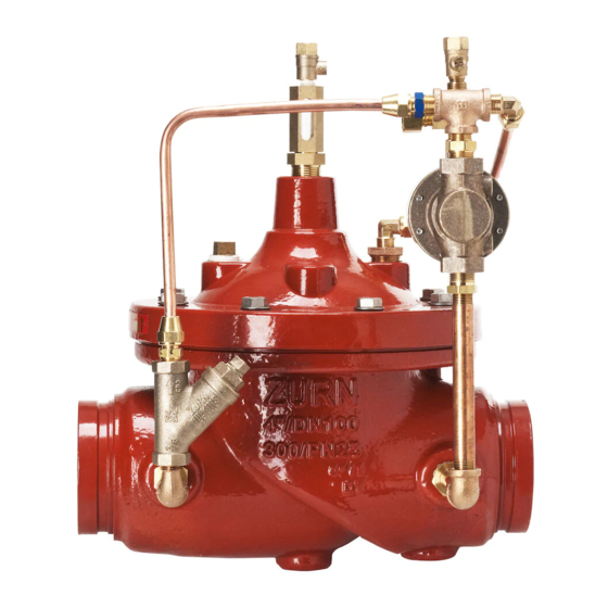
Model ZW215FP
Fire Pump Suction Control Valve
Globe and Angle Pattern Bodies
2", 2-1/2", 3", 4", 6", 8", & 10"
Installation
DESCRIPTION
The Zurn Wilkins Model ZW215FP Fire Pump Suction Control Valve
is designed specifically for Fire Suppression Systems to prevent fire
pumps from over-drawing from the water supply resulting in damage
to the pump or the supply network because of very low or negative
pressures on the suction side of the fire pump. The pilot assembly
reacts quickly to increases and decreases of suction pressure.
The control valve will close if suction pressure drops below the set
pressure. The control valve will open again once suction pressure
rises to the control valve set pressure and will modulate to keep
the suction pressure at the set pressure until supply increases. In
addition the Model ZW215FP comes standard with red epoxy coat-
ing internally and externally for corrosion protection, as well as a
test cock on the sensing port for quick bleeding of sensing line. The
ZW215FP is available in both globe and angle pattern bodies.
Installation / Start-up
INSTALLATION
NOTE: Prior to installation of the ZW215FP, ensure that all debris
is flushed out the piping system before installed.
1.
During the installation of a ZW215FP in a sprinkler system, verify
installation meets requirements of local law or the Authority Having
Jurisdiction.
2.
Allow for adequate space around the valve for making adjust-
ments and servicing.
3. Position the ZW215FP in line matching the direction of flow as
indicated on the valve model tag with the proper direction of flow in
the system. The valve must be installed on the discharge side of the
fire pump.
4.
Connect pilot control sensing connection to the suction side of
the pump by minimum 3/8 in diameter tubing.
5.
Once control valve and sensing line are installed, double check
all fasteners/bolts in the pilot system and on main valve are tight and
there is no damage prior to pressurizing system.
NOTE: Pressure in some applications can be very high so be
thorough in checking and inspecting for proper installation and
makeup.
6.
Zurn Wilkins valves are designed to operate in both the vertical
and horizontal positions. However, it is recommended that ZW215FP's
6" and larger, be installation in the horizontal position. The horizontal
positioning of the larger valves avoids premature wear due to mass of
plunger assemblies as well as allows for greater accessibility during
annual inspections, and maintenance.
START-UP
CAUTION: To prevent personnel injury and damage to equip-
ment check that downstream venting is adequate prior to
start-up and test procedures. All adjustments under pressure
should be made slowly. If the main valve opens or closes too fast
it may cause surging in upstream piping.
!
WARNING: Cancer and Reproductive Harm - www.P65Warnings.ca.gov
!
ADVERTENCIA: Cáncer y daño reproductivo - www.P65Warnings.ca.gov
!
AVERTISSEMENT: Cancer et néfastes sur la reproduction - www.P65Warnings.ca.gov
®
Start-up
Maintenance Instructions
Class 150 Flanged
Max 250 psi Inlet
1.
2.
valve and pilot system of air. To vent air, partially open or loosen the
highest plugs or fittings in the system. The ZPI valve position indicator
is a great location, as it has a test cock at the top to vent air pressure.
It may be necessary to bleed system more than once. After removal of
air in the system tighten all loose fittings. NOTE: If valve is installed
vertically, it will be necessary to loosen some upper cover bolts
until you have vented all the air from the cover chamber.
3.
a gauge in the test cock on the sensing line to read the suction pres-
sure.
4.
can be turned by hand. Note: A small amount of spring force must
be maintained so the spring and spring discs do not fall out of
alignment. Do not loosen the pilot adjustment screw completely.
Note: The control valve should open and allow a lot of water to
flow. If there is no flow, continue turning the pilot adjustment screw
counterclockwise. Once water is flowing through the control valve it
is necessary to lower the suction pressure below the desire set pres-
sure. One can cause the suction pressure to decrease by increasing
flow through the pump or using a valve upstream of the pump suction
to throttle water to the pump.
5.
sure, slowly turn the pilot valve adjustment screw clockwise. As the
screw is tightened the control valve will slowly start to close causing
upstream pressure to increase. Continue turning adjustment screw
clockwise until suction pressure is stable at the desired set pressure.
6.
verify proper operation of the ZW215FP, view the valve during normal
operation and check the valve for minimum suction pressure setting.
Adjustments can be made at anytime.
1747 Commerce Way, Paso Robles, CA 93446 Phone:855-663-9876 Fax:805-238-5766
ZW215FP
ZW215FPG
Grooved
Max 300 psi Inlet
FM
APPROVED
Pressurize the upstream side of the ZW215FP.
As the valve is filling with water, it is necessary to bleed the main
Install a pressure gauge on the suction side of the pump or install
Loosen the pilot adjustment screw until the adjustment screw
Once suction pressure is below desired minimum suction pres-
Tighten adjustment screw jam nut once step 4 is completed. To
®
ZW215FPY
Class 300 Flanged
Max 300 psi Inlet
ZW215FPTH
Threaded
Max 300 psi Inlet
ZURN WILKINS
1
www.zurn.com
Advertisement

Subscribe to Our Youtube Channel
Related Manuals for Zurn Wilkins ZW215FP


Summary of Contents for Zurn Wilkins ZW215FP
- Page 1 Installation / Start-up INSTALLATION Pressurize the upstream side of the ZW215FP. NOTE: Prior to installation of the ZW215FP, ensure that all debris is flushed out the piping system before installed. As the valve is filling with water, it is necessary to bleed the main During the installation of a ZW215FP in a sprinkler system, verify valve and pilot system of air.
- Page 2 Operation The Zurn Wilkins ZW215FP utilizes a pressure relief pilot valve that installs on the discharge side of the control circuitry. The pilot Model PV-RLF is a direct acting, normally closed, spring loaded, diaphragm actuated valve. The operation of the ZW215FP begins with accurately sizing the valve, then fine tuning the control circuitry by adjusting the PV-RLF to open at the desired suction pres- sure.
- Page 3 In addition to complying with NFPA 25 every five years, sched- components as necessary. uled preventative maintenance and inspection is highly recom- mended. ZURN WILKINS recommends annual inspection of Next, clean and inspect the seat inside the main valve body. valves for leaks and proper operation. It is also recommended...
- Page 4 Relief Pilot Seat 5. On the other side of the stem place the small washer, o-ring, plunger (with the rubber facing away from the spacer), and nut. ZURN WILKINS 1747 Commerce Way, Paso Robles, CA 93446 Phone:855-663-9876 Fax:805-238-5766 ISZW215FP (REV. C 6/17)
Need help?
Do you have a question about the ZW215FP and is the answer not in the manual?
Questions and answers