Advertisement
Model FCIS
Flood Control Integrated System (1 1/4" - 10")
Installation
Installation
Refer to ZW206 installation instruction and backflow
preventer (975XL2, 375MS) installation instructions for
specific information on these valves during install and
startup.
Flush line to remove all debris before installing any valve.
For ease of repair and maintenance, a shutoff valve
should be installed upstream of the FCIS assembly if one
is not conveniently located nearby.
If a strainer is being installed, it should be located up-
stream of the Model FCIS.
Next the Model ZW206 solenoid control valve with EST
mounted to cover should be installed. Note the direction
of flow arrow on the inlet flange or inlet side of cover.
The backflow preventer is now installed downstream of
the ZW206 and connected to the downstream piping. A
gasket set, nipple or grooved coupling is provided to con-
nect the ZW206 to the backflow preventer.
If necessary, an air gap adapter fitting can be installed to
the relief valve discharge port to direct water to the drain.
A drain MUST be installed in the room to remove dis-
charged water. The Model FCIS will shutdown the water
supply to prevent a catastrophic failure of the backflow
preventer from flooding the room. It will not prevent small
discharges from the relief valve. (A water sensor or float
switch that provides contact closure during flooding can
also shutdown the water if flooding is caused by other
equipment in the mechanical room. Contact factory for
details.)
The solenoid valve, backflow preventer, and water sys-
tem can be filled and leak tested without having to wait
for an electrician to connect power to the EST box.
The solenoid valve is furnished standard as normally
open (NO.) This means the valve will open to allow water
WARRANTY: ZURN WILKINS Valves are guaranteed against defects of material or workmanship when used for the services recommended. If
in any recommended service, a defect develops due to material or workmanship, and the device is returned, freight prepaid, to ZURN WILKINS within
12 months from date of purchase, it will be repaired or replaced free of charge. ZURN WILKINS' liability shall be limited to our agreement to repair or
replace the valve only.
! WARNING: Cancer and Reproductive Harm - www.P65Warnings.ca.gov
! ADVERTENCIA: Cáncer y daño reproductivo - www.P65Warnings.ca.gov
! AVERTISSEMENT: Cancer et néfastes sur la reproduction - www.P65Warnings.ca.gov
®
Start-up
Testing
1747 Commerce Way, Paso Robles, CA 93446 Phone:855-663-9876 Fax:805-238-5766
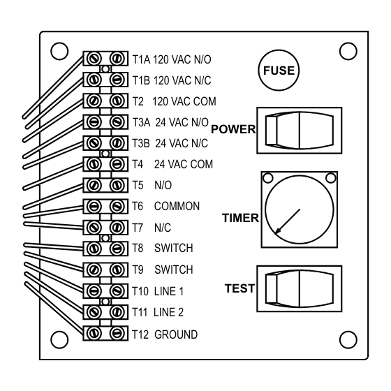
POWER LIGHT
T1A 120 VAC N/O
T1B 120 VAC N/C
T2 120 VAC COM
T3A 24 VAC N/O
T3B 24 VAC N/C
T4 24 VAC COM
T5 N/O
T6 COMMON
T7 N/C
T8 SWITCH
T9 SWITCH
T10 LINE 1
T11 LINE 2
T12 GROUND
The black wire on the EST should already be connected
to the solenoid pilot. If it not, then the pilot coil should be
plugged into the end of the black cable. The screw in the
center of the plug should be tightened to prevent it from
coming accidentally unplugged.
There is a yellow cable that comes from the EST. This
should be uncoiled and connected to the black socket
on the backflow preventer relief valve located below the
backflow. Line up the keyway in the plug and socket,
then push the plug into place. Next tighten the threaded
lock ring at the end of the cable to the socket to prevent it
from coming unplugged.
flow unless power is applied to the solenoid. A normally
closed (NC) solenoid valve is an option. To determine the
type of valve you have, look at the ZW206 tag on the inlet
flange. NO or NC should appear after the model number.
If you have an NO valve, then the system can be filled by
simply open the shutoff valve upstream of the FCIS.
ALARM LIGHT
FUSE
POWER
TIMER
TEST
ZURN WILKINS
www.zurn.com
®
1
Advertisement
Table of Contents

Subscribe to Our Youtube Channel
Related Manuals for Zurn Wilkins FCIS


Summary of Contents for Zurn Wilkins FCIS
- Page 1 ZURN WILKINS within 12 months from date of purchase, it will be repaired or replaced free of charge. ZURN WILKINS' liability shall be limited to our agreement to repair or replace the valve only.
- Page 2 The solenoid valve cover must be vented of air for proper for the FCIS to operated properly. operation; refer to ZW206 instruction sheet. If left for an extended duration in manual override, it may be wise to hang a note pointing this out to others There is a red knob on the solenoid pilot.
- Page 3 This will also allow you to see if the ZW206 is closing properly and tightly. Refer the individual instruc- tion sheets for the ZW206 and backflow preventer for suggested maintenance on those valves. ZURN WILKINS ® 1747 Commerce Way, Paso Robles, CA 93446 Phone:855-663-9876 Fax:805-238-5766 www.zurn.com...
Need help?
Do you have a question about the FCIS and is the answer not in the manual?
Questions and answers