Advertisement
Quick Links
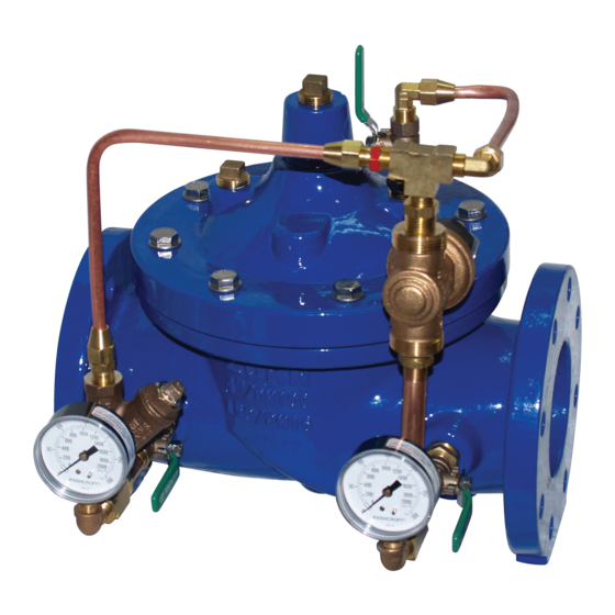
Model ZW209Q
Pressure Reducing Valve with Downstream Surge Protection
Globe and Angle Pattern Bodies
1 1/4", 1 1/2", 2", 2-1/2", 3", 4", 6", 8", 10", 12", 14" & 16"
*Contains a weighted average lead content less than 0.25% for wetted surfaces
Installation
Installation / Start-up
NOTE: Flushing of all pipe lines is to be performed to remove all
debris prior to installing valve.
NOTE: If installation is subject to very low flow or potentially static
conditions it is recommended a pressure relief valve (1/2" minimum)
be installed downstream of the pressure reducing valve for additional
system protection.
1. For making adjustments and servicing allow for adequate space around
the valve before installing valve.
2. When installing a ZW209Q, gate valves installed on both inlet and outlet
are recommended for maintenance allowing for isolation of valve.
3. Position the valve in line matching the direction of flow as indicated on
the valve model tag with the proper direction of flow in the system. Once
attached to line, double check all fasteners/bolts in the pilot system and on
main valve are tight and there is no damage prior to pressurizing system.
NOTE: Pressure in some applications can be very high so be thor-
ough in checking and inspecting for proper installation and makeup.
4. Zurn Wilkins valves are designed to operate in both the vertical and
horizontal positions. However, it is recommended that ZW209Q 6" and
larger, be installed in the horizontal position. The horizontal positioning
of the larger valves avoids premature wear due to the mass of plunger
assemblies as well as allows for greater accessibility during annual inspec-
tions, and maintenance.
ZW209Q SCHEMATIC
STANDARD COMPONENTS
1 Main Valve
2 850MXL Isolation Valve
3 SXL "Wye" Type Strainer
4 Pressure Gauge
5 Restriction Tube Fitting
6 PRXL Pressure Reducing Control
7 PV-RLF Pressure Relief Valve
START-UP
CAUTION: To prevent personnel injury and damage to equipment check
that downstream venting is adequate prior to start-up and test proce-
dures. All adjustments under pressure should be made slowly while
under flowing conditions.
!
WARNING: Cancer and Reproductive Harm - www.P65Warnings.ca.gov
!
ADVERTENCIA: Cáncer y daño reproductivo - www.P65Warnings.ca.gov
!
AVERTISSEMENT: Cancer et néfastes sur la reproduction - www.P65Warnings.ca.gov
®
LEAD-FREE*
Troubleshooting
OPTIONAL FEATURES
C 40XL2 Hydraulic Check w/
Isolation Valve
L SC1 Closing Speed Control
O SC2 Opening Speed Control
Z ZPI Valve Position Indicator
1747 Commerce Way, Paso Robles, CA 93446 Phone:855-663-9876 Fax:805-238-5766
Maintenance Instructions
1. Open isolation valves (2) in the pilot system (see ZW209Q sche-
matic).
2. Then slowly open the upstream shutoff valve only enough to fill
main valve assembly and pilot system. Prior to pressurizing the valve
assembly it is also recommended that a ZPI valve position indicator be
installed to aid in verifying proper valve movement.
3. As the valve is filling with water, it is necessary to bleed the main valve
and pilot system of air. To vent air, partially open or loosen the highest
plugs or fittings in the system. The ZPI valve position indicator is a great
location, as it has a test cock at the top to vent air pressure. It may be
necessary to bleed system more than once. After removal of air in the
system tighten all loose fittings. NOTE: If valve is installed vertically, it
will be necessary to loosen some upper cover bolts until you have
vented all the air from the cover chamber.
4. Before setting valve, if valve is equipped with SC1 Flow controls (O
or L on ZW209Q schematic) it is necessary to completely back out the
set screw.
5. Turn the surge protection pilot (relief pilot) adjustment screw clock-
wise until the pilot spring is compressed completely so the pressure
reducing pilot can be set first.
6. At this point with the upstream shutoff valve open, slowly open the
downstream shut off valve. Flow will begin to occur and pressure should
build up in valve and eventually stabilize.
7. Next it is advisable to flow water through the valve to ensure all air
has escaped from system. With water flowing through the valve, set the
pressure reducing pilot 10 to 15 psi higher than the desired pressure
reducing set pressure so the surge protection pilot can be set. To adjust
the pressure reducing pilot, loosen jam nut on adjustment screw and
either turn adjustment screw in (to increase outlet pressure) or out (to
decrease outlet pressure).
8. Now set the surge protection pilot. With water still flowing through
the main valve, start to turn the surge protection pilot adjustment screw
counterclockwise until the downstream pressure drops 5 to 10 psi.
Tighten the jam nut on the surge protection pilot.
9. Lower the downstream pressure to the desired setting by adjusting
pressure reducing pilot. Once pilot is set, tighten the jam nut.
10. To verify proper operation of ZW209Q close and open downstream
shut off valve several times to ensure downstream pressure is stable at
set pressure.
11. After pilot system has been adjusted and the valve is properly regu-
lating, the main valve opening and closing speed controls (O or L) can
be adjusted as needed.
12. When setting speed controls, turning the adjustment screw into the
speed control will restrict the amount of flow through the needle valve.
Depending on whether the control is for opening or closing (refer to
ZW209Q schematic) the control will either slow the opening or closing
of the main valve when the adjustment screw is turned into the speed
control. Adjust as needed and tighten jam nut.
®
ZURN WILKINS
1
www.zurn.com
Advertisement

Related Manuals for Zurn Wilkins ZW209Q


Summary of Contents for Zurn Wilkins ZW209Q
- Page 1 1. For making adjustments and servicing allow for adequate space around installed to aid in verifying proper valve movement. the valve before installing valve. 3. As the valve is filling with water, it is necessary to bleed the main valve 2. When installing a ZW209Q, gate valves installed on both inlet and outlet and pilot system of air. To vent air, partially open or loosen the highest are recommended for maintenance allowing for isolation of valve. plugs or fittings in the system. The ZPI valve position indicator is a great 3. Position the valve in line matching the direction of flow as indicated on...
-
Page 2: Troubleshooting
Troubleshooting The following troubleshooting information in Tables 1 - 3 deals strictly with the ZW209Q valve and pilot systems. It is recommended to verify that the pilot system is properly functioning before troubleshooting the main valve. All troubleshooting can be performed without removing the cover. It is also recommended to permanently install a model ZPI valve position indicator. TABLE 1. PRESSURE REDUCING PILOT SYSTEM TROUBLESHOOTING PROBLEM POSSIBLE CAUSES CORRECTIVE ACTION 1. Outlet Pressure Low 1. No spring compression in Pilot 1. Tighten adjusting screw 2. Damaged spring in Pilot 2. Disassemble and replace 3. Clogged "Wye" Strainer 3. Remove, clean, and/ or replace 4. - Page 3 PRESSURE PILOT REDUCING CHECK position on the indicator. Compare distance of the open mark to 1. With pressure on the inlet of the ZW209Q close the 3 iso- the close mark and compare to Table 3. lation ball valves connecting to the surge protection pilot.
-
Page 4: Maintenance Instructions
Either way it is recommended that the valve be disassembled and inspected (refer to “Disassembly” section). 7. To perform the diaphragm check using the vale stem tool, Maintenance Instructions PREVENTATIVE MAINTENANCE The Zurn Wilkins ZW200 models require minimal maintenance. in a while it is possible that the assembly will require the use of a However, it is highly recommended to schedule annual inspec- rubber mallet or pry bars to dismantle the assembly. If this is the tions and to have a repair kit on hand before work begins. - Page 5 (ft-lbs) ‡ SEAT REPAIR KIT 1-1/4" 1-1/2" 2" 20-25 2-1/2" 25-35 3" 35-45 4" 40-50 6" 50-60 8" 60-70 10" 70-75 12" 110-115 14" 170-175 16" 230-240 ZURN WILKINS ® 1747 Commerce Way, Paso Robles, CA 93446 Phone:855-663-9876 Fax:805-238-5766 www.zurn.com...
- Page 6 4. Slide the stem through the spacer with the diaphragm Spring Disc Relief Pilot Spacer assembly on the spacer side with a circular groove on Spring Sensing Hole Gasket the top surface. Pilot Bell O-ring, Buna Nitrile, NSF Listed 5. On the other side of the stem place the small washer, o-ring, plunger (with the rubber facing away from the 3x8-16 Jam Hex Nut Relief Pilot Seat spacer), and nut. ZURN WILKINS ® 1747 Commerce Way, Paso Robles, CA 93446 Phone:855-663-9876 Fax:805-238-5766 www.zurn.com...
-
Page 7: Flow Characteristics
150 + 20 = 170 psi. When inlet pressure is below set point, the outlet pressure will be the pressure at the inlet minus the friction loss. ZURN WILKINS ® 1747 Commerce Way, Paso Robles, CA 93446 Phone:855-663-9876 Fax:805-238-5766 www.zurn.com...
Need help?
Do you have a question about the ZW209Q and is the answer not in the manual?
Questions and answers