Table of Contents
Advertisement
Quick Links
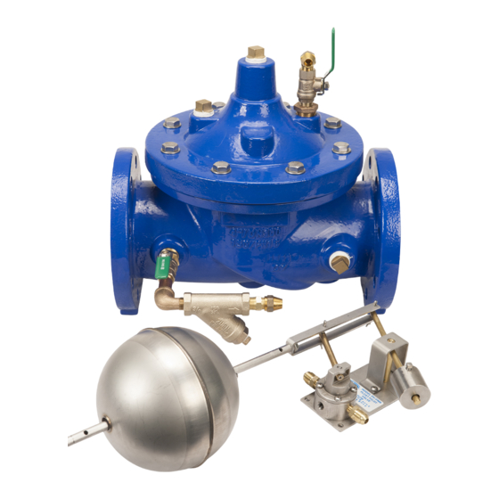
Model ZW204
Non-Modulating Float Valve
1 1/4", 1 1/2", 2", 2-1/2", 3", 4", 6", 8" & 10"
Installation Troubleshooting Maintenance Instructions
Installation / Start-up
DESCRIPTION
The Zurn Wilkins Model ZW204 Non-Modulating Float Operated
Control Valve is an automatic control valve designed to be fully
open or fully closed in response to the position of the float. The
float ball will be placed in a tank where it will be raised or lowered
by the fluid level. The valve will be fully open when the fluid level is
at a preset low point and will fully close when the fluid level is at a
preset high point. If the float valve is being used to flow water out
of instead of into the reservoir, the float pilotry can be configured
to have the valve fully open at a preset high point and fully closed
at a preset low point. If desired, switch line from port A to B on
the float valve and plug port A. The Float Pilot valve is set up for
remote liquid level control as standard. With the VM option, the
float pilot can be mounted on the valve.
NOTE: Flushing of all pipe lines is to be performed to remove
all debris prior to installing valve.
1. Install a control valve, orifice, or other flow restricting device
downstream of the ZW204 if discharge pressure is greater than
20 psi. This will prevent the valve from exceeding maximum
flow, cavitating, or causing other damage to valve or system
from high water velocities.
2. For making adjustments and servicing allow for adequate space
around the valve before installing valve.
3. When installing a ZW204, gate valves installed on both inlet and
outlet are recommended for maintenance allowing for isolation of
valve.
4. Position the main valve in line matching the direction of flow as
indicated on the valve model tag with the proper direction of flow
in the system. Once attached to line, double check all fasteners/
bolts in the pilot system and on main valve are tight and there is
no damage prior to pressurizing system.
NOTE: Pressure in some applications can be very high so be
thorough in checking and inspecting for proper installation
and makeup.
NOTE: Upstream pressure should be at least 10 psi greater
than downstream hydrostatic pressure when valve is
closed.
5. The float ball and rod assembly must be mounted in the verti-
cal position above the water in a tank or reservoir.
Note: A stilling well is required to surround the float in
tanks or reservoirs which are subject to waves of any kind.
Verify float has adequate clearance to move freely in all
float positions.
6. Go to step 7 if installing a ZW204 with valve mounted pilot.
When installing a ZW204 with remote pilot, route tubing from
the main valve to the float valve according to the schematic dia-
grams on page 3. Port P on the float valve should be connected
®
to the inlet of the main valve. Port A should be connected to the
main valve cover (or accelerator pilot cover if installing an 8 or
10 inch valve.)
Note: When mounting the float pilot above the main valve,
verify pressure at the float pilot is 5 psi or greater to ensure
proper operation.
7. Zurn Wilkins valves are designed to operate in both the verti-
cal and horizontal positions. However, it is recommended that
ZW209 6" and larger, be installation in the horizontal position.
The horizontal positioning of the larger valves avoids premature
wear due to the mass of plunger assemblies as well as allows
for greater accessibility during annual inspections, and mainte-
nance.
START-UP
CAUTION: To prevent personnel injury and damage to
equipment check that downstream venting is adequate pri-
or to start-up and test procedures. If the main valve closes
too fast it may cause surging in upstream piping.
1. Open isolation valves (2) in the pilot system (see ZW204
schematics).
2. Slowly open the upstream shutoff valve only enough to fill
main valve assembly and pilot system. Prior to pressurizing the
valve assembly it is also recommended that a ZPI valve position
indicator be installed to aid in verifying proper valve movement.
3. As the valve is filling with water, it is necessary to bleed the
main valve and pilot system of air. To vent air, partially open or
loosen the highest plugs or fittings in the system. The ZPI valve
position indicator is a great location, as it has a test cock at the
top to vent air pressure. It may be necessary to bleed system
more than once. After removal of air in the system tighten all
loose fittings.
4. If valve is equipped with speed controls (O or L on ZW204
schematic) it is necessary to back out the set screw a minimum
of 3 turns from initial set point.
5. At this point with the upstream shutoff valve partially open,
slowly open the downstream shut off valve. Flow will begin to
occur and pressure should build up in valve and eventually
stabilize.
6. Next it is advisable to flow water through the valve to ensure all
air has escaped from system.
1747 Commerce Way, Paso Robles, CA 93446 Phone:855-663-9876 Fax:805-238-5766
®
ZURN WILKINS
1
www.zurn.com
Advertisement
Table of Contents

Subscribe to Our Youtube Channel
Related Manuals for Zurn Wilkins ZW204


Summary of Contents for Zurn Wilkins ZW204
- Page 1 NOTE: Pressure in some applications can be very high so be 4. If valve is equipped with speed controls (O or L on ZW204 thorough in checking and inspecting for proper installation schematic) it is necessary to back out the set screw a minimum and makeup.
- Page 2 Adjust as needed and tighten jam nut. In general a closing speed control PARTS LIST on a ZW204 should be at least 3 turns out from the furthest ITEM DESCRIPTION closed position to prevent high tank overflow.
-
Page 3: Standard Components
CAUTION: Do not service valve while under pressure. and the pilot is operating correctly go to the “Diaphragm Check” When performing diagnosis checks on the ZW204 and the and “Diaphragm Movement Check” sections. valve is fully open, high flow rates and high downstream 4. - Page 4 Replace or repair any parts as necessary. seal or a damaged seal. If water does stop flowing and the measured valve movement does not match Table. 3, then there ZURN WILKINS ® 1747 Commerce Way, Paso Robles, CA 93446 Phone:855-663-9876 Fax:805-238-5766...
-
Page 5: Maintenance Instructions
PREVENTATIVE MAINTENANCE 8. To remove the seat, on valves 6” and smaller the seat is The Zurn Wilkins ZW200 models require minimal maintenance. threaded into the body and will require a seat removal tool. Care However, it is highly recommended to schedule annual inspec- should be taken when removing the seat to avoid damaging. - Page 6 SEAT ‡ COVER STUDS (8" AND LARGER) SEAT O-RING ‡ BODY BODY PLUGS * RUBBER REPAIR KIT ITEMS † COMPLETE REPAIR KIT ITEMS ‡ SEAT REPAIR KIT ZURN WILKINS ® 1747 Commerce Way, Paso Robles, CA 93446 Phone:855-663-9876 Fax:805-238-5766 www.zurn.com...
- Page 7 12. Reinstall into the pilot system once maintenance is com- pleted. For further assistance or ordering replacement parts go to www.zurn.com or call product support 877-222-5356 ZURN WILKINS ® 1747 Commerce Way, Paso Robles, CA 93446 Phone:855-663-9876 Fax:805-238-5766 www.zurn.com...
- Page 8 VALVE SEAT ROLL PIN SS VALVE STEM SCREW VALVE STEM O-RING VALVE STEM WASHER SS VALVE SPRING VALVE COVER O-RING VALVE BODY VALVE NUT SS SECTION A-A ZURN WILKINS ® 1747 Commerce Way, Paso Robles, CA 93446 Phone:855-663-9876 Fax:805-238-5766 www.zurn.com...
-
Page 9: Flow Characteristics
Note: If the valve is to be used for continuous flow, supply adequate back pressure to operate the valve below the "Damage Zone" shown on the "Pressure Reduction Limit" chart. If the valve discharges to atmosphere adequate back pressure is very important, contact Zurn Wilkins for assistance. ZURN WILKINS ®...
Need help?
Do you have a question about the ZW204 and is the answer not in the manual?
Questions and answers