Advertisement
Quick Links
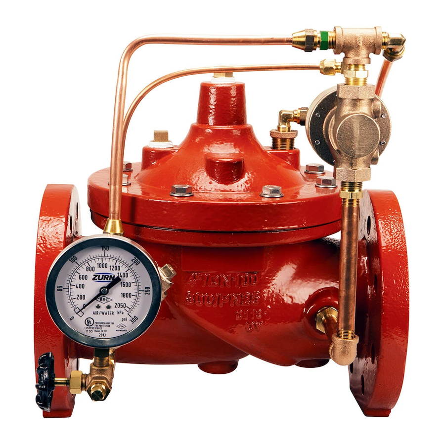
Model ZW205FP
Fire Pump Relief Valve
Globe and Angle Pattern Bodies
2", 2-1/2", 3", 4", 6", 8", & 10"
Installation
DESCRIPTION
The Zurn Wilkins Model ZW205FP Fire Pump Pressure Relief Valve
is designed specifically for Fire Suppression Systems to relieve high
system pressures. The pilot assembly reacts quickly to increases
of upstream pressure to prevent damage to system piping, valves,
and sprinklers while maintaining positive pressure on fire pumps. As
the water demand increases in the fire suppression system the relief
valve will start to close, directing more water to suppress fires. The
relief valve will maintain the upstream pressure at the set pressure as
long as maximum flow rates of the valve are not exceeded. The Zurn
Wilkins Model ZW205FP is design to open quickly and close slowly to
prevent upstream pressure surges. In addition the Model ZW205FP
comes standard with red epoxy coating internally and externally for
corrosion protection, as well an inlet pressure gauge for quick and easy
maintenance or repair. The ZW205FP is available in both globe and
angle pattern bodies.
Installation / Start-up
INSTALLATION
NOTE: Prior to installation of the ZW205FP, ensure that all debris is
flushed out the piping system before installed.
1.
During the installation of a ZW205FP in a sprinkler system, Underwriter
Laboratories (UL) requires NFPA 13 "Standard for Installation of Sprinkler
Systems" and NFPA 20 "Standard for the Installation of Stationary Pumps
for Fire Protection" be followed.
2.
Upon installation UL also requires that the ZW205FP be tested in
accordance with NFPA 13 or NFPA 20. Thereafter the valve shall be in-
spected, tested, and maintained in accordance to NFPA 25 "Standard for
the Inspection, Testing, and Maintenance of Water-Based Fire Protection
Systems".
3.
For making adjustments and servicing allow for adequate space
around the valve.
4.
Position the ZW205FP in line matching the direction of flow as indi-
cated on the valve model tag with the proper direction of flow in the system.
Once attached to line, double check all fasteners/bolts in the pilot system
and on main valve are tight and there is no damage prior to pressurizing
system.
NOTE: Pressure in some applications can be very high so be thor-
ough in checking and inspecting for proper installation and makeup.
6.
Zurn Wilkins valves are designed to operate in both the vertical and
horizontal positions. However, it is recommended that ZW205FP's 6" and
larger, be installation in the horizontal position.
The horizontal positioning of the larger valves avoids premature wear due to
mass of plunger assemblies as well as allows for greater accessibility during
annual inspections, and maintenance.
!
WARNING: Cancer and Reproductive Harm - www.P65Warnings.ca.gov
!
ADVERTENCIA: Cáncer y daño reproductivo - www.P65Warnings.ca.gov
!
AVERTISSEMENT: Cancer et néfastes sur la reproduction - www.P65Warnings.ca.gov
®
Start-up
Maintenance Instructions
START-UP
CAUTION: To prevent personnel injury and damage to equipment
check that downstream venting is adequate prior to start-up and
test procedures. All adjustments under
pressure should be made slowly. If the main valve opens or closes
too fast it may cause surging in upstream piping.
1.
a ZPI valve position indicator be installed to aid in verifying proper valve
movement. Pressurize the upstream side of the ZW205FP.
2.
valve and pilot system of air. To vent air, partially open or loosen the high-
est plugs or fittings in the system. The ZPI valve position indicator is a
great location, as it has a test cock at the top to vent air pressure. It may
be necessary to bleed system more than once. After removal of air in the
system tighten all loose fittings. NOTE: If valve is installed vertically, it
will be necessary to loosen some upper cover bolts until you have
vented all the air from the cover chamber.
3.
different procedures. Choose one based on the capabilities of the fire
protection system
a. Close all discharge lines from the fire pump so all flow goes
through the ZW205FP. Loosen the pilot adjustment screw all the way
to lower the set relief pressure. Turn on the fire pump to pressurize the
upstream side of the ZW205FP. Note: The control valve should open
and allow a lot of water to flow. If there is no flow, continue turning
the pilot adjustment screw counterclockwise. Once water is flowing
through the control valve, slowly turn the pilot valve adjustment screw
clockwise. As the screw is tightened the control valve will slowly start to
close causing upstream pressure to increase. Continue turning adjust-
ment screw clockwise until upstream pressure is stable at the desired
relief set pressure.
1747 Commerce Way, Paso Robles, CA 93446 Phone:855-663-9876 Fax:805-238-5766
ZW205FP
ZW205FPG
Class 150 Flanged
Grooved
Max 250 psi Inlet
Max 300 psi Inlet
LISTED
FM
APPROVED
Prior to pressurizing the valve assembly, it is also recommended that
As the valve is filling with water, it is necessary to bleed the main
One can adjust the set pressure of the control valve by one of three
®
ZW205FPY
Class 300 Flanged
Max 300 psi Inlet
ZW205FPTH
Threaded
t
Max 300 psi Inle
ZURN WILKINS
1
www.zurn.com
Advertisement

Related Manuals for Zurn Wilkins ZW205FP


Summary of Contents for Zurn Wilkins ZW205FP
- Page 1 Class 300 Flanged long as maximum flow rates of the valve are not exceeded. The Zurn Max 250 psi Inlet Max 300 psi Inlet Max 300 psi Inlet Wilkins Model ZW205FP is design to open quickly and close slowly to ZW205FPTH prevent upstream pressure surges. In addition the Model ZW205FP Threaded LISTED...
- Page 2 Operation The Zurn Wilkins ZW205FP utilizes a pressure relief pilot valve that installs on the discharge side of the control circuitry. The pilot Model PV-RLF is a direct acting, normally closed, spring loaded, diaphragm actuated valve. The operation of the ZW205FP begins with accurately sizing the valve, then fine tuning the control circuitry by adjusting the PV-RLF to open at the desired upstream pressure.
- Page 3 Replace any damaged uled preventative maintenance and inspection is highly recom- components as necessary. mended. ZURN WILKINS recommends annual inspection of valves for leaks and proper operation. It is also recommended Next, clean and inspect the seat inside the main valve that a repair kit with a new diaphragm, disc, and o-rings be on body. If excessive water deposits are present, fine grit sand pa-...
- Page 4 5. On the other side of the stem place the small washer, 3x8-16 Jam Hex Nut Relief Pilot Seat o-ring, plunger (with the rubber facing away from the spacer), and nut. ZURN WILKINS 1747 Commerce Way, Paso Robles, CA 93446 Phone:855-663-9876 Fax:805-238-5766 ISZW205FP-2-10 (REV. C 6/17) www.zurn.com...
Need help?
Do you have a question about the ZW205FP and is the answer not in the manual?
Questions and answers