
Related Manuals for Barnstead International Harvey Hydroclave MC8


Summary of Contents for Barnstead International Harvey Hydroclave MC8
- Page 1 Harvey ® Hydroclave MC8 Hydroclave MC10 Steam Sterilizer (With Optional Non-Recirculating System) OWNER AND OPERATOR MANUAL LT1203X1 • 5/11/04...
-
Page 2: Table Of Contents
Table of Contents Introduction................................4 Operation Overview ............................4 Hydroclave MC8 and MC10 Steam Sterilizer ..................4 Drying Cycle ............................5 Operator Maintenance ..........................6 Daily ..............................6 Weekly..............................6 Safety Information ..............................7 Declaration of Conformity ..........................7 Description of Symbols on the Equipment ....................8 General Description ............................10 Intended Use ..............................10 General Usage............................10 Operating Features ............................10... - Page 3 ABLE OF ONTENTS Cleaning Door Gasket ..........................31 Weekly ................................31 Cleaning Chamber, Trays and Rack ....................31 Cleaning and Disinfecting Exterior Surfaces..................32 Every 25 Cycles............................32 Cleaning Reservoir ..........................32 Draining Reservoir..........................32 Cleaning Reservoir Filter........................33 Cleaning Chamber Filter Screen......................33 When Required ............................34 Emptying Non-Recirculating Collection Bottle..................34 Cleaning Printer Recess (MC10) ......................34 Replacing Door Gasket ........................35 Every 6 Months ............................36...
-
Page 4: Introduction
Introduction As leaders in the field of sterilization, our goal is to engi- neer and manufacture safe, efficient, quality sterilization products. We are certain you will agree that this sterilizer meets our goal. Regardless of how well a piece of equipment is designed, misuse, abuse, or neglect will deny its owner the safe, effi- cient, quality service expected. -
Page 5: Drying Cycle
NTRODUCTION What happens when the cycle starts? • The water fill valve opens and the proper amount of water automatically flows from the reservoir into the chamber. • The water in the chamber begins to heat. As the water turns to steam, the temperature and pressure increase, forcing air from the cham- ber. -
Page 6: Operator Maintenance
NTRODUCTION Operator Maintenance It is important to establish the maintenance schedule called for in the Operator Maintenance section of this manual. Daily Before each days use: Check the water level in the reser- voir. Refill with distilled or deionized water if needed. Clean the door gasket and its mating surface. -
Page 7: Safety Information
Declaration of Conformity Caution Barnstead International hereby declares under its sole Cautions alert you to a possibility of responsibility that this product conforms with the technical damage to the equipment. requirements of the following standards (applies to units... -
Page 8: Description Of Symbols On The Equipment
AFETY NFORMATION Description of Symbols on the Equipment Hot Surface Printer Receptacle Attention: Consult Accompanying Documents (Refer to Warning and Caution notes in this manual.) Type B Equipment, Class I (Refer to IEC Standard 601-1.) OFF (Only for a part of equipment.)* ON (Only for a part of equipment.)* Paper Feed * Does not disconnect equipment from mains voltage (AC... - Page 9 Reservoir Fill Funnel Control Panel MC10 Printer Non-Recirculating (Optional) Water Accessory (Optional) Drain Tube Open Locking Leveling Lock Handle Feet Printer Reservoir Receptacle Filter (MC8) Screen Water Fill Port & Chamber Filter Screen Reservoir Door Drain Valve Gasket Pressure Push To Relief Release Valve...
-
Page 10: General Description
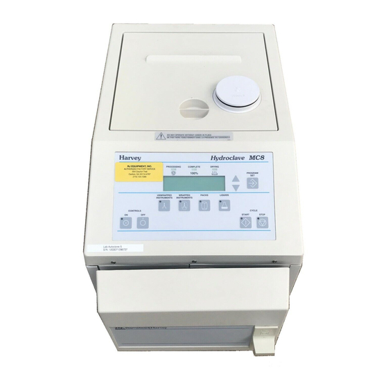
General Description Intended Use The Hydroclave MC8 and MC10 Sterilizers have been designed for use in medical and dental offices, hospitals, clin- ics, laboratories and other facilities where a variety of materials require processing. This steam sterilizer can be used for wrapped or unwrapped instruments, linen packs, and liquids. - Page 11 ENERAL ESCRIPTION Cycle Phase Indicators Harvey Hydroclave MC8 Cycle Select Switches Figure 1 Control Panel...
- Page 12 ENERAL ESCRIPTION Support Flange Tray Rack (MC8 - Part No. 265002) (MC10 - Part No. 2-513025) Large Tray (Part No. 2-67811) Small Tray (Part No. 265001) MC10 Figure 2 Standard Accessories IMS ® Cassette Four (Not Sold By B/T) Tray Rack Wrapped (MC8 - Part No.
-
Page 13: Printer
ENERAL ESCRIPTION Printer The MC8 printer is a separate unit connected to the steril- izer by a plug-in cable and a separate power supply. The optional MC10 printer is an integral part of the Control Panel. Non-Recirculating Printer Water Accessory Figure 4 MC8 Printer Standard MC8 and MC10 sterilizers discharge steam back... - Page 14 ENERAL ESCRIPTION We recommend the use of process indicators such as the B|T Check Indicator within each package of each cycle. For additional assurance that minimum sterilizing conditions have been achieved, a biological indicator such as B|T Sure should be used at least once a week. Description Part No.
-
Page 15: Operation
Operation Press Controls ON. Fill Reservoir. Warning Patient Safety Zone: Do not oper- ate this sterilizer within 6 ft. (2 m) of Load Chamber. patient treatment point. Lock Door. Select Cycle. Press START. Open Door to Dry.* Remove Load. * Optional—Drying phase, if selected, will start automati- cally without opening the door. -
Page 16: Power On/Controls On
PERATION Power On/Controls On When the sterilizer is plugged in and the con- Note trols are off, the time and date will be dis- If time and date are incorrect, reset played. the clock/calendar. Press Controls ON switch to turn on the con- trol panel. -
Page 17: Filling Reservoir
PERATION Filling Reservoir Caution Add distilled or low quality deionized water (minimum 0.5 Use only distilled or low quality megohm/cm, maximum 1.5 megohm/cm) to the reservoir deionized water (minimum 0.5 up to the fill line. The MC8 reservoir holds approximately 3 megohm/cm, maximum 1.5 liters;... -
Page 18: Filling Non-Recirculating Tank (Option)
PERATION Note The cooling tank must be connected to the sterilizer before filling the tank with water. Filling Non-Recirculating Tank Note (Option) Do not operate sterilizer unless the Remove the cap from the cooling tank. cooling tank is filled with distilled or deionized water and attached to the Fill the cooling tank with distilled or deionized sterilizer. -
Page 19: Installing Overflow Tube (Optional)
PERATION Note Installing Overflow Tube The sink or drain must be below the level of the cooling tank for the (Optional) water drain. If the sterilizer is located within 5 ft. (1.5 m) of a sink or drain, the overflow tube may be used. The collection bottle Warning will not require emptying while the automatic overflow is Volatile Reaction: Do not use this... -
Page 20: Load Chart
PERATION Load Chart - e l . s t . s t l l a l a t e t t e t t " 5 , " - e l - e l " 6 " 0 " 6 "... -
Page 21: Preparing Items For Sterilization
PERATION Preparing Items for Sterilization • Clean and dry items thoroughly before placing in the sterilizer. Ultrasonic cleaning is recommend- ed to remove stubborn debris. • After cleaning, rinse instruments thoroughly with deionized or distilled water. Inspect instruments to ensure that all debris has been removed. •... -
Page 22: Selecting Cycle
PERATION Note Selecting Cycle Whether using the two tray, four-tray, or IMS cassette rack, items being When the controls are turned on, the settings for the pre- processed should be evenly distrib- vious cycle will be displayed. uted on each tray or cassette and within the sterilization chamber. -
Page 23: Starting Cycle
PERATION Press the UP or DOWN arrows to increase or Note decrease the drying time. The open door drying time is limited to the selected closed door drying Press the PROGRAM/SET switch to save the time. If zero is selected, open door drying time value. -
Page 24: Open Door Drying
PERATION Open Door Drying Note Unlock and open the door. Two beeps will Closed door drying will stop when sound and the indicator lights will turn off. the door is opened. When START is pressed to begin open door drying, Push down on the door latch so that the door the timer will be reset to the pro- will remain ajar. -
Page 25: Additional Information
Additional Information Cancel Cycle To cancel a sterilizing cycle or drying phase in progress, Note press the STOP switch. If a cycle is canceled prematurely, reprocess the load. Failure to do so may result in non-sterile goods. Emergency Power Off To remove all power from the sterilizer, press the OFF Warning switch, then unplug the power cord. -
Page 26: Diagnostic Messages
Diagnostic Messages f l l " f " , t i e l i P " " T " " f l l . r i l i f... -
Page 27: Troubleshooting
Troubleshooting s l l z i l " 0 z i l z i l • L " " t r L " " g • s l l • " 4 " 0 e l i... -
Page 28: Printer
Printer Installation Push & Connect printer cable to receptacle on back of sterilizer. Hold Plug power cable/transformer into wall outlet. MC10 The printer is factory installed. If a printer is added later, it Figure 15 should be installed by an authorized service technician. On/OFF Paper Feed Switch Operation The printer provides hard copy documentation of each... -
Page 29: Paper Roll Replacement
RINTER Be Sure Feed End is Shiny Note Cut Straight Across Metal Cut feed end of new paper roll Strip Spindle straight across for ease of replace- Slot ment. Paper Roll Replacement To remove the old paper roll core, lift up and snap out. -
Page 30: Printer Removal (Mc10)
RINTER Printer Removal (MC10) Lift the printer out of the recess. Rest the printer on the top cover while cleaning the recess. It is not necessary to disconnect the printer cables. When installing the printer, tuck the excess cable into the recess. Lift the Printer Out Wipe With... -
Page 31: Operator Maintenance
Operator Maintenance Hot Surface Burn Hazard: Be sure sterilizer is cool before cleaning door gasket Daily and mating surface. Cleaning Door Gasket Wipe the door gasket and mating surfaces daily with a Hot Surface clean damp cloth. Do not use abrasive cleaners on the Burn Hazard: Be sure sterilizer is gasket or mating surface. -
Page 32: Cleaning And Disinfecting Exterior Surfaces
PERATOR AINTENANCE Cleaning and Disinfecting Caution Exterior Surfaces Do not use steam to disinfect or The exterior surfaces may be cleaned and disinfected with clean the sterilizer cabinet. Extreme agents typically found in dental and medical offices. Wipe high temperatures could cause the surface clean with mild detergent and disinfect in plastic parts to become distorted. -
Page 33: Cleaning Reservoir Filter
PERATOR AINTENANCE Remove the reservoir lid and wipe the inside reservoir with a clean damp cloth and mild disinfectant. Do not use abrasive cleaners. Note Wipe the reservoir clean of any disinfectant Reservoir cleaning is not required as residue. often on units with non-recirculating feature. -
Page 34: When Required
PERATOR AINTENANCE When Required Note Emptying Non-Recirculating The fill port is the bottom hole in the Collection Bottle back of the chamber. The top hole is Empty the collection bottle when the water in the bottle for the temperature probe and reaches the FULL mark. -
Page 35: Replacing Door Gasket
PERATOR AINTENANCE Note The gasket is adhered to the door plate and must be pulled loose. Replacing Door Gasket Open the sterilizer door and remove the hex nut in the center of the gasket retainer and Note remove the gasket retainer and gasket. Allow about an hour for the silicone sealant to set, then run a no-load Clean surface of the door plate, new gasket... -
Page 36: Every 6 Months
PERATOR AINTENANCE Every 6 Months Warning The pressure relief (safety) valve, located on the back of Burn Hazard: Steam blow-off will be the cabinet, releases excess pressure (over 45 psi) from discharged when the ring on the relief the chamber. valve is pulled. -
Page 37: Cleaning Non-Recirculating Water Cooling Tank
PERATOR AINTENANCE Cleaning Non-Recirculating Water Hot Surface Cooling Tank The non-recirculating water cooling tank should be Burn Hazard: Do not clean the tank drained and rinsed out every six months. Do not clean when the sterilizer is in operation. Allow the tank when the sterilizer is in operation. -
Page 38: Recommended Spare Parts
Recommended Spare Parts Warning Note Electrical shock Hazard: Do not remove Refer to Service Manual LT1203X2 for access covers. This equipment should piping schematic, and servicing proce- only be serviced by qualified personnel. dures. Refer to Parts Catalog LT1203X3 for illustrated parts list. The following parts should be kept on hand for prompt replacement when needed. -
Page 39: Installation
Installation Note Warning The MC8 weighs 55 lbs. (25 kg); the MC10 Explosion Hazard: Do not locate this steril- weighs 70 lbs. (32 kg). The sterilizer izer in areas where explosive anesthetics should be lifted by two persons and trans- are used or stored. -
Page 40: Non-Recirculating Water Accessory Installation
NSTALLATION Non-Recirculating Water Accessory Installation Step 2 Step 1 Remove cap from Attach discharge hose non-recirculating assembly from cooling tank to non-recirculating discharge port on discharge port. rear of sterilizer and discard. Tighten nut finger tight, plus 1/4 turn with wrench. 1/4 Turn Step 3 Automatic... -
Page 41: Setting The Clock/Calendar
NSTALLATION Setting the Clock/Calendar Plug in the power cord, but do not press con- trols ON. The software will perform a self-test, then the time and date will be displayed. Press PROGRAM/SET switch. a. The hour will flash: 12:00 AM JAN 01 1998 Use the UP arrow to set the hour ahead or the down arrow to set it back. - Page 42 NSTALLATION Use the arrows to set the month. Press PRO- GRAM/SET to store. e. The day will flash: 12:00 AM JAN 01 1998 Use the arrows to set the day. Press PRO- GRAM/SET to store. f. The year will flash: 12:00 AM JAN 01 1998 Use the arrows to set the year.
- Page 43 NSTALLATION Activate the non-recirculating feature: Warning Non-Recirculating Option must be Press and release OFF switch, then installed before proceeding. press again and hold. Do not release. Note This operation requires the use of two hands. You must tell the steriliz- Press and hold PROGRAM/SET er that the non-recirculating feature switch.
- Page 44 NSTALLATION Press PROGRAM/SET after each of the follow- ing messages. Caution LOG ERXX XXXXX The following messages will DATE TIME appear. Failure to follow these instructions may result in improper operating conditions. Press PROGRAM/SET DIAGNOSTICS Press PROGRAM/SET 12 HOUR CLOCK Press PROGRAM/SET TEMPERATURE CELSIUS...
- Page 45 NSTALLATION Press PROGRAM/SET MODEL MC8 OR MC10 Press PROGRAM/SET STANDARD UNIT Press PROGRAM/SET When RECIRCULATE is displayed, press either the up or down arrow to change to NON-RECIRCULATE. RECIRCULATE Press PROGRAM SET STERILIZE Press STOP (This will revert back to the main display menu, time and date.)
-
Page 46: Technical Data
Technical Data MC10 Cabinet Size 13-1/2” W x 16” H x 23” L 16” W x 18” H x 23” L (33 mm W x 406mm H x 559mm L) (406mm W x 457mm H x 584mm L) Chamber Size 8”... -
Page 47: Appendix
Appendix Voltage Conversion Warning (Dual Voltage Models Only) Unplug power cord before removing (Spec plate must state 115/230 Volt) any access panels. Voltage conver- Remove the left side panel (4 screws), the sion should be performed by a quali- pressure relief valve deflection cover (MC8 fied service technician. -
Page 48: 115 Vac To 230 Vac
PPENDIX 115 VAC to 230 VAC Parts Required • Two 8 Amp time delay fuses (Part No. 264306) • Suitable 230 VAC plug or plug adapter On the Power I/O PC Board: Remove jumpers from J5 to J7 and J3 to J8. Install jumper from J7 to J8. - Page 49 PPENDIX Figure 32 Power I/O PC Board (230 VAC)
- Page 50 PPENDIX Figure 33 MC10 Printer Power Supply Board (230 VAC)
-
Page 51: 230 Vac To 115 Vac
PPENDIX 230 VAC to 115 VAC Parts Required • two 15 AMP time delay fuses (Part No. 266058) • jumper for Power I/O Board • jumper for Printer Power PC Board • suitable 115 VAC plug or plug adapter On the Power I/O PC Board: Remove jumper from J7 to J8. - Page 52 PPENDIX Figure 34 Power I/O Board (115 VAC)
- Page 53 PPENDIX Figure 35 MC10 Printer Power Supply Board (115 VAC)
-
Page 56: Two-Year Limited Warranty
Two Year Limited Warranty Barnstead International (“BARNSTEAD”) warrants that if a product manufactured by Barnstead shall be free of defects in materials and workmanship for two (2) year from the first to occur of (i) the date the product is sold by BARNSTEAD or (ii) the date the product is purchased by the original retail customer (the “Commencement...
Need help?
Do you have a question about the Harvey Hydroclave MC8 and is the answer not in the manual?
Questions and answers