
Subscribe to Our Youtube Channel
Related Manuals for Barnstead International Harvey Hydroclave MC8


Summary of Contents for Barnstead International Harvey Hydroclave MC8
- Page 1 Service Manual Harvey ® Hydroclave MC8 Hydroclave MC10 Steam Sterilizer 2-350409 • 9/27/04...
-
Page 2: Table Of Contents
Table of Contents Safety Information ..............................4 Alert Signals ................................4 General Specifications ............................5 General Information ............................6 Controls ON/OFF ..............................7 Cycle Select Switches ............................7 Cycle Start/Stop ..............................7 Programming Switches ............................8 Display Window ..............................8 Cycle Phase Indicators ............................8 Principles of Operation............................9 Cycle Description ..............................9 Controls Description ............................11 Trouble Analysis ..............................14 Fuse Replacement ............................14... - Page 3 ABLE ONTENTS Door Handle and Latch Replacement ......................58 Door Cover Replacement ..........................59 Appendix ................................60...
-
Page 4: Safety Information
Safety Information These symbols with related notes appear throughout this manual. Alert Signals Warning Warnings alert you to a possibility of per- sonal injury. Caution Cautions alert you to a possibility of damage to the equipment. Note Notes alert you to pertinent facts and conditions. -
Page 5: General Specifications
General Specifications MC10 Cabinet Size 13-1/2” W x 16” H x 22” L 16” W x 18” H x 23” L (330 mm W x 406mm H x 559mm L) (406mm W x 457mm H x 584mm L) Chamber Size 8”... -
Page 6: General Information
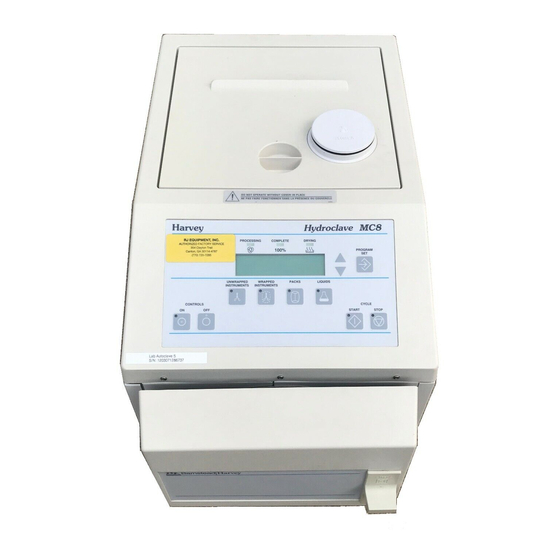
General Information Cycle Phase Indicators Harvey Hydroclave MC8 Cycle Select Switches Figure 1 Control Panel... -
Page 7: Controls On/Off
ENERAL NFORMATION Controls ON/OFF • CONTROLS ON: Turns ON the Control Panel. Note When the power cord is plugged in and • CONTROLS OFF: Turns OFF the Control the controls are OFF, the Control Panel Panel. will display the time. Cycle Select Switches •... -
Page 8: Programming Switches
ENERAL NFORMATION Programming Switches • PROGRAM/SET: Used to set clock/calendar, select cycle parameters in memory. • UP AND DOWN ARROWS: Used with the PRO- GRAM/SET switch to select operating proce- dures. Display Window A two-line LCD displays cycle parameters, counts down exposure and drying times, and displays messages. -
Page 9: Principles Of Operation
Principles of Operation Cycle Description Note For detailed cycle information, refer to Controls ON (Standby) the cycle phase diagrams in the Service Data section. The vent valve is open when the unit is in standby mode. The heater is turned on to warm up the chamber. Fill Phase When CYCLE START is pressed, there is a 15 second delay and then the fill valve is open for timed period. - Page 10 RINCIPLES OF PERATION Reservoir Exposure Phase The exposure set point is maintained for a timed period. The heater is controlled to maintain the chamber tempera- Fill ture and pressure. Exhaust Phase Steam Dry Goods (Recirculating Unit) The heater is turned off and the fill (exhaust) valve is opened.
-
Page 11: Controls Description
RINCIPLES OF PERATION Controls Description The electronic controls include the following assemblies: • Power I/O PC Board 2A • Control PC Board 3A • Control Panel 4A • Printer 5A (optional) • Transformer PC Board 6A (optional MC10 printer) Power Input The customer supply input (115 or 230 VAC) is routed to the EMI filter, Power I/O PC Board, and Transformer PC Board. - Page 12 RINCIPLES OF PERATION The input from temperature sensor 1RT is an analog volt- age that is applied to a conditioning circuit which produces coarse and fine control voltages. These voltages are applied to the microprocessor for precise control of the chamber temperature.
- Page 13 RINCIPLES OF PERATION Customer Supply Input Filter (See Chart) Noise Filter Power I/O Board 1Sol Vent Thermal Switch 2Sol 1HTR/2HTR Fill Heater 1SSR 3SOL Non-Rc Solid State Relay Control Panel Temperature Probe Control Board Door Switch Pressure Transducer Serial Data Customer Supply Transformer Board...
-
Page 14: Trouble Analysis
Trouble Analysis Fuse Replacement Caution Factory setup mode should only be Main Fuses used by authorized service personnel. The main fuses are located on the back panel of the steril- izer. 115 VAC units have one 15A fuse. 230 VAC units have two 8A fuses. - Page 15 ROUBLE NALYSIS Diagnostic Messages u l i e l i . t i o l l ¡ 0 . t r . t i l a i v i t . t i ¡ 5 l i f l l a t l i f...
- Page 16 ROUBLE NALYSIS Diagnostic Messages c t i l l e l l e ¡ 0 . t i l l i t . t i P " " T l l i t , t r...
-
Page 17: Diagnostics Mode
ROUBLE NALYSIS Diagnostics Mode Caution When diagnostics mode has been enabled in the factory Factory setup mode should only be used setup mode, the following features will be activated: by authorized service personnel. • Automatic Cycle Start. If the door is not opened within 30 seconds after a cycle is completed, the software will automatically start another cycle. -
Page 18: Power Supply Circuits
ROUBLE NALYSIS Power Supply Circuits Ñ , t i l , t i l t s i c t i... - Page 19 ROUBLE NALYSIS Figure 7 Power Supply Circuits...
-
Page 20: Heater Control Unit
ROUBLE NALYSIS Heater Control Unit o l l y t i c t i y t i . t i... - Page 21 ROUBLE NALYSIS Figure 8 Solenoid Control Circuits Figure 9 Heater Control Circuit...
-
Page 22: Solenoid Control Circuits
ROUBLE NALYSIS Solenoid Control Circuits Ñ ) t l l i o ) t l l i o l l i f... -
Page 23: Component Check Procedures
ROUBLE NALYSIS Component Check Procedures y f i . ) r e i l t i l i l a . t i c t i c t i c t i y f i : y l c t i c t i c t i y l i... - Page 24 Component Check Procedures , f f z i l l l a . c i z i l z i l ) - ( , s l Note When +5VDC is measured across the control terminals (J+ and J-) of the SSR, there should be 0 VAC across the SSR AC terminals.
- Page 25 ROUBLE NALYSIS Component Check Procedures l i r ¡ 0 ¡ 2 l l i...
- Page 26 ROUBLE NALYSIS Figure 11 Transducer and Switch Input Circuits...
-
Page 27: Service Data
Service Data Flow Diagram Recirculating Unit Reservoir Water Supply 1 Sol Vent Solenoid Valve Reservoir Pressure Pressure Filter Safety Valve Chamber Pressure Transducer Manual Reservoir Drain Valve Temperature Transducer 3 Sol 1HTR Reservoir Filter Fill/Drain 2 Sol Solenoid Valve Figure 12 Piping Schematic - Recirculating Unit... - Page 28 ERVICE Flow Diagram Non-Recirculating Unit Reservoir Water Supply 1 Sol Vent Solenoid Valve Reservoir Pressure Pressure Filter Safety Valve Chamber Pressure Transducer Manual Reservoir Drain Valve Temperature Transducer Drain Solenoid Valve 3 Sol 1HTR Condensation 2 Sol Fill Collector Solenoid Valve Figure 13 Non-Recirculating Unit...
- Page 29 ERVICE Dry Goods Cycle MC8 & MC10 Non-Recirculating Unit Recirculating Unit Figure 14 Cycle Phase Diagram - Dry Goods Cycle...
- Page 30 ERVICE Liquid Cycle MC8 & MC10 Non-Recirculating Unit Recirculating Unit Figure 15 Cycle Phase Diagram - Liquids Cycle...
- Page 31 ERVICE Note Thermal Switch 2S is mounted on the left side of the chamber as views from the front of the sterilizer. The leads from the Power I/O Board to the thermal switch are orange. MC10 Printer (Option) Control PC Board Control Panel Power I/O PC Board...
- Page 32 ERVICE Reservoir Vent Cover Port Reservoir Filter Screen Vent Solenoid Valve Manual Drain Valve Chamber Drain Filter Screen Fill/Drain Non-Recirculating Solenoid Valve Pressure Discharge Port Relief Drain Solenoid Valve Valve (Non-Recirculating Option) Figure 17 Piping Components...
- Page 33 ERVICE Figure 18 Electrical Schematic...
- Page 34 ERVICE Figure 19 MC8 Electrical Schematic...
- Page 35 ERVICE Figure 20 MC8 Electrical Schematic...
- Page 36 ERVICE Figure 21 Electrical Schematic...
- Page 37 ERVICE Fill/Drain Non-Recirculating Fault Power On Heater Vent Solenoid Drain Solenoid DS10 Solenoid Torque U3 Torque U2 TP8 TP7 10 In/Lbs. Use TP6 10 In/Lbs. Use TP3 Ground Ground Figure 22 Power I/O PC Board Component Locations...
-
Page 38: Led Indicators
ERVICE LED Indicators l l i Test Points ± ±... - Page 39 ERVICE Front View Power On DS10 Back View Temperature Test Points Sensing Circuit Adjustment R3 (See Page 4-8) Figure 23 Control PC Board Component Locations...
-
Page 40: Adjustments
ERVICE Test Points ± ± Adjustments... -
Page 41: Led Indicators
ERVICE LED Indicators Switch Panel Functions... - Page 42 ERVICE Figure 24 Transformer Board Component Locations...
- Page 43 ERVICE Figure 25 Transformer PC Board (115 VAC) Figure 26 Power I/O PC Board (115 VAC)
- Page 44 ERVICE Figure 27 Transformer PC Board (230 Vac) Figure 28 Power I/O PC Board (230 Vac)
-
Page 45: Setup And Adjustments
Setup and Adjustments Voltage Conversion Warning To configure the unit for 115 VAC operation: Shock Hazard: Unplug the power cord On the Power I/O PC Board connect jumper before moving jumpers. from J7 to J5 and from J3 to J8. Connect heater common (white) to J11, heater (black) 1 to J13 and heater (black) 2 to J14. - Page 46 ETUP AND DJUSTMENTS Clock set and cycle parameter mode may be used by the operator. Factory setup mode should only be accessed by qualified service technicians. Clock Set Sequence Set the hour by pressing the up or down arrow. Press PROG/SET to stir the value in the memo- 12:00 AM JAN 01 1998 Set the minute, then press PROG/SET.
- Page 47 ETUP AND DJUSTMENT Clock Set Mode Clock set mode is used to set the time and date. • To enter clock set mode, press PROG/SET in CONTROLS OFF mode. • To exit clock set mode at any time, press CYCLE STOP. Cycle Parameter Mode Cycle parameter mode is used to program the exposure and drying times (if desired).
- Page 48 ETUP AND DJUSTMENTS Factory Setup Mode Factory setup mode is used to: Warning • view the error log Select STANDARD UNIT when setting up a Harvey sterilizer. If LAB UNIT is • enable or disable diagnostics mode selected, it will be possible to program cycle parameters that will not result in •...
- Page 49 ETUP AND DJUSTMENTS Time Format: Select 12 HOUR CLOCK or 24 HOUR CLOCK. Press PROG/SET. 12 HOUR CLOCK Date Format: Select M/D/Y (month/day/year) or D/M/Y (day/month/year). Press PROG/SET. DATE FORMAT M/D/Y Temperature Units: Select CELSIUS (°C) or FAHRENHEIT (°F). Press PROG/SET. TEMPERATURE CELSIUS Pressure Units: Select PSI (pounds per...
- Page 50 ETUP AND DJUSTMENTS Unit Size: Select MC8 (8” diameter) or MC10 (10” diameter). Press PROG/SET. MODEL MC8 OR MC10 10. Model Configuration: Select Harvey. CONFIGURATION HARVEY 11. Unit type: Select STANDARD UNIT (fixed tem- Warning perature) or LAB UNIT (selectable 102 to Select STANDARD UNIT when setting 135°C) unit.
-
Page 51: Control Pc Board Adjustments
ETUP AND DJUSTMENTS Control PC Board Adjustments Temperature Sensing Circuit Calibration Equipment Required: • digital voltmeter (dvm), 4-1/2 digit, 0.03% accuracy • five-decade resistance box, 0.1 to 1000 ohms decades, 0.025% accuracy 0.03% precision resistor, 1500.5 ohms Calibration Check Unplug RTD from J12 on Control PC Board. Note Allow the chamber to cool down to Measure RTD resistance. -
Page 52: Display Contrast Adjustment
ETUP AND DJUSTMENTS Calibration Procedure Measure reference voltage at TP4. Use TP3 ground. Reference voltage should be +5.000 ±0.010 VDC. Replace Control PC Board if refer- ence voltage is out of tolerance. Connect resistance box to J12-1 and J12-2. set box to 1500.5 ohms. -
Page 53: Repair And Replacement
Repair and Replacement Cabinet Removal Warning Shock Hazard: Disconnect power cord Side Panels from power source before removing panels or servicing internal parts. Remove two screws at the lower edge of the side panel. Pull the panel down and outward at the bot- tom until upper edge disengages from the top cover. -
Page 54: Power I/O Pc Board
EPAIR AND EPLACEMENT Power I/O PC Board Power I/O Replacement PC Board Unplug power cord from the power source. Transformer PC Board (MC10) Remove the side and back panels from the ster- ilizer. Unplug all wires and cables from Power I/O PC Board. -
Page 55: Control Panel
EPAIR AND EPLACEMENT Control Panel Replacement Remove side panels from sterilizer. Remove cover shield from Control PC Board. Disconnect ribbon cable from J2 on Control PC Board. Remove Control PC Board. Remove Switch Panel. Route ribbon cable of replacement Switch Panel through slot. -
Page 56: Pressure Transducer
EPAIR AND EPLACEMENT Pressure Transducer Warning Do not wrench or apply stress to the Replacement plastic body of the transducer. Unplug power cord. Remove right side access panel. Using two wrenches, disconnect pressure trans- ducer from fitting. Apply one wrench to fitting and the other wrench to the transducer connec- tor. -
Page 57: Thermal Cut-Off Switch
EPAIR AND EPLACEMENT Thermal Cut-Off Switch Replacement Unplug power cord. Caution Disconnect switch from Power I/O PC Board. Water in reservoir and piping may be HOT. Care should be taken to prevent Carefully remove insulation around thermal burns. switch. Remove switch from heater extrusion. From Reservoir Vent Install replacement switch. -
Page 58: Chamber Door
EPAIR AND EPLACEMENT Note Gasket will be adhered to doorplate. Silicon (RTV) Sealant Gasket Chamber Door Gasket Retainer Door Gasket Replacement Hex Nut Remove the hex nut in the center of the gasket retainer and remove the gasket and gasket Hole retainer. - Page 59 EPAIR AND EPLACEMENT Door Cover Replacement Remove the door handle as described in Door Handle and Latch Removal. Remove the hex nut in the center of the door Fold Gasket Over gasket retainer and remove the GASKET To Access Screws Remove Door RETAINER ONLY.
- Page 60 Appendix How to Use This Table Find the measured RTD resistance in the RTD (Ohms) column. ¡ ( ) ¡ ( ) ¡ ( ) ¡ ( ) ¡ ( If the measured resistance is between two val- ues, note the upper and lower value. Note the coarse voltage that corresponds to the lower resistance value.
- Page 64 2555 Kerper Boulevard P.O. Box 797 Dubuque, Iowa 52001-0797 Phone: 563-556-2241 or 800-553-0039 Fax: 563-589-0516 E-mail: mkt@barnstead.com www.barnstead.com...
Need help?
Do you have a question about the Harvey Hydroclave MC8 and is the answer not in the manual?
Questions and answers