Be Modern EVOLV GAS FIRES 520 Slimline Inset Installation And Servicing Instructions

Be Modern EVOLV GAS FIRES 520 Slimline Inset Installation And Servicing Instructions

Inset live fuel effect

Advertisement

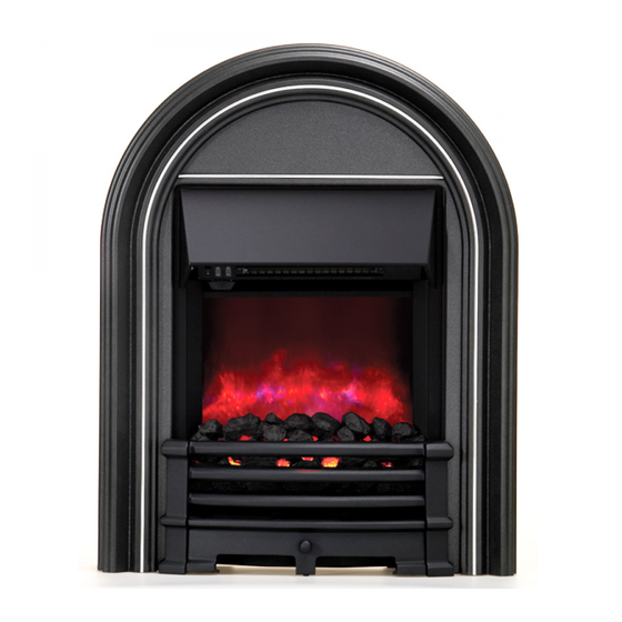
Inset Live Fuel Effect
MODEL 520 Slimline Inset
For use on Natural Gas at a supply pressure of 20mbars in G.B./I.E
INSTALLATION AND SERVICING
INSTRUCTIONS
(For user's instructions, please see reverse)
These instructions must be handed to the user
to be kept in a safe place for future reference
Part No. 200379
Issue 4.
GC No. 32-210-14
Patent application No. 0123387.3
Be Modern Customer Care, Bede Industrial Estate
Jarrow, Tyne and Wear, NE32 3BE
Tel: (0191) 489 8266 option 4.
- 1 -

Advertisement

Table of Contents
loading
Need help?

Need help?

Do you have a question about the EVOLV GAS FIRES 520 Slimline Inset and is the answer not in the manual?

Questions and answers

Subscribe to Our Youtube Channel

Summary of Contents for Be Modern EVOLV GAS FIRES 520 Slimline Inset

  • Page 1 Part No. 200379 Issue 4. GC No. 32-210-14 Patent application No. 0123387.3 Be Modern Customer Care, Bede Industrial Estate Jarrow, Tyne and Wear, NE32 3BE Tel: (0191) 489 8266 option 4. - 1 -...
  • Page 2: Table Of Contents

    The model number of this appliance is as stated on the rating plate. In the event of any problems, please telephone (0191) 430 0901. This product has been manufactured by Be Modern Appliances, Pilgrim Way, Bede Industrial Estate, Jarrow, NE32 3HG. Important notice to installer The cream fibre board, which may be supplied with this appliance, may discolour on its initial startup.
  • Page 3: Important Notes

    Important Safety Notes FAILURE TO COMPLY WITH ANY OF THESE REGULATIONS COULD LEAD TO PROSECUTION AND DEEM THE WARRANTY INVALID. This appliance has been designed to work on natural gas. It is law that all appliances using natural gas shall be installed by a competent person who shall fit in accordance with the current Gas Safety Regulations, the relevant British Standard Installation specifications, Codes of Practice and in accordance with the manufacturer’s instructions and the various recommendations contained in the following regulations: -...
  • Page 4: Site Requirements

    Site Requirements Please read these instructions carefully before installation Any exposed brickwork should be inspected and repaired where necessary. The opening should be from 390 mm to 430mm wide and from 540mm to 568mm high and a minimum depth for precast and 5’’...
  • Page 5: Ventilation

    This fire requires a hearth constructed of non-combustible materials and must conform to the minimum dimensions. Diagram 1C Diagram 1C Diagram 1D The hearth must be at least 12mm thick and the top surface should not be less than 50mm above the surrounding floor level, or have a fixed fender 50mm high, surrounding the hearth.
  • Page 6: Fire Box Installation

    Fire Box Installation ENSURE that the gas supply is isolated before you commence the installation of this appliance. Read all previous sections of these instructions prior to starting the installation of this appliance. Having previously prepared the installation site as detailed, remove the fire components from the carton. You must protect floor covering with a dust sheet or similar.
  • Page 7: Fitting The Ceramic Fibre

    Fitting the Ceramic Fibre Depending on which model you have purchased your fire will be supplied with either coal or pebble fibres. Fitting the rear fibre bed Place the rear fibre bed into position, ensuring that slot on its underside has correctly located into the up stand just behind the burner.
  • Page 8: Trim Installation

    Trim Installation Depending on the model of fire you have purchased, your fire may have been supplied with either a one-piece magnetic trim or a three-piece clip on trim. If there are separate instructions supplied with the trim please refer to those. One-Piece Magnetic Trim The one-piece trim is delivered with the trim attached, by magnets.
  • Page 9: Fret Fixing Instructions

    Fret Fixing Instructions Depending on the model of fire you have purchased, your fire may have been supplied with a fret that locates on keyhole brackets. If there are separate instructions supplied with the fret please refer to those. Use the two M5 screws and two M5 nuts to fix fret to fire as follows: Thread nut onto screws up to the screw head.
  • Page 10: Operating The Appliance

    Operating the Appliance The gas control valve is situated at the base of the fire tray behind the ash pan cover along with the data information badge. The gas control valve incorporates a thermoelectric oxygen depletion device, which in the event of a problem with the flue performance causing the spillage of products into the room, the valve will automatically shut off the gas and turn off the fire.
  • Page 11: Commissioning The Fire

    Commissioning the Fire Check for Spillage The appliance must be tested for spillage. Close all the doors and windows in the room containing the appliance. The appliance must be completely installed with all the ceramics fitted including the coals, the front and fret and the fire surround. Light the fire and turn it to its High setting for 5 min.
  • Page 12: Short Spares List

    Spares List No Of Description Part No GC No 1 set Rear Fibre Bed (black) 101761 H50-710 One Piece Front Ceramic (black) Loose Coal Bag 1 set Rear Fibre Bed (cream coloured) 101763 H50-711 One Piece Front Ceramic (cream coloured) Loose Pebble Bag (cream coloured) 1 set Rear Fibre Bed (black)
  • Page 13 USER’S INSTRUCTIONS To the Customer Annual checking of the flue and regular servicing of this fire is recommended to ensure continued safe operation. Once a year is the recommended service interval. British Gas/Scottish Gas can carry out this work. Important Notes: This appliance has been designed to work on natural gas. It is the law that all appliances using natural gas shall be installed by a competent person, who shall fit in accordance with current Gas Safety Regulations, the relevant British Standard Installation Specifications, Code of Practice and in accordance with the manufacturer’s instructions and the various recommendations contained in the building regulations issued by the Department of the...
  • Page 14 The model number of this appliance is as stated on the rating plate. In the event of any problems, please telephone (0191) 489 8266 option 4. This product has been manufactured by Be Modern Appliances, Pilgrim Way, Bede Industrial Estate, Jarrow, NE32 3HG.

This manual is also suitable for:

Abbey gas fireAvantgarde gas fire

Table of Contents