Table of Contents
Advertisement
Quick Links
Advertisement
Table of Contents

Related Manuals for TCS QD2040b


Summary of Contents for TCS QD2040b
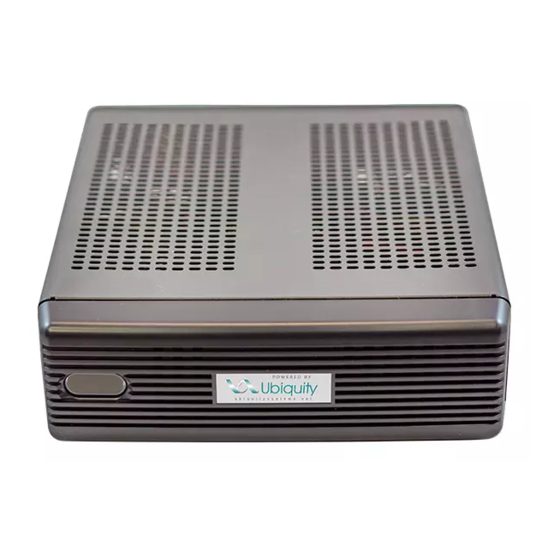
- Page 1 Installation Manual QD2040b The QD2040b Ubiquity Cloud Site Gateway connects the site controller network with the Ubiquity Cloud™ server. Ubiquity Cloud Site Gateway 2800 Laura Lane • Middleton, WI 53562 | 800.288.9383 • fax: 608.836.9044 | www.tcsbasys.com v.2105...
-
Page 2: Table Of Contents
Contents Installation ......................3 Introduction ............................3 Material List.............................3 Mounting ..............................3 Input Connections ..........................3 QD2040b Power and Communication Connections Diagram .............4 RS-485 Network Wiring ........................4 Three-Wire Network Wiring ............................5 Two-Wire Network Wiring ............................. 6 Startup ..............................7 Troubleshooting ............................ 7 Power LED Does Not Light Up ............................7 No Communications with Controllers on the Network .................. -
Page 3: Installation
• Wall Mounting Bracket Mounting The QD2040b is designed to be hung on a wall via the mounting screw holes in each unit. It may also be set on a shelf or table. Do not allow the mounting screws to touch the circuit board inside the enclosure. -
Page 4: Qd2040B Power And Communication Connections Diagram
A 120 Ω terminating resistor should be placed at each of the two ends of the network directly across the “A” and “B” wires. If the QD2040b will be at one end of the network, hard-wire a 120 Ω terminating resistor across the “A” and “B” terminals of the QD2040b (See "Three-Wire Network Wiring"... -
Page 5: Three-Wire Network Wiring
Last in Daisy Chain Earth Ground Only at one end Three-Wire Diagram Shielded, twisted three-conductor com- QD2040b at end of the network. NOTES: munications wiring with one end earth If using more than 64 controllers, grounded. (120 Ω balancing resistors use the second RS-485 port or provided.) -
Page 6: Two-Wire Network Wiring
(120 Ω balancing resistors If using more than 64 controllers, use the second RS-485 port or provided.) additional QD1010 adapters. QD2040b in the middle of the net- Shielded, twisted two-conductor com- work. Each controller must use the munications wiring with one end earth same baud rate and be assigned grounded. -
Page 7: Startup
No Communications with Controllers on the Network Make sure the baud rate selection for the QD2040b is set to match the baud rate of all the controllers on each port net- work (the default communication speed of the serial bus is 9600). All controllers on the network must have a unique ad- dress, excluding the reserved address ‘248’. -
Page 8: No Communication With Rs-485 Ports (Com 1 And 2), Ubiquity Time-Out, Or No Data
RS-485 lines. A set of LEDs on each of the RS-485 ports on the QD2040b allow the building occupant to view operational status of the serial communication integrated board: •... -
Page 9: Configuration
The Software Status section contains software/application-related information that identifies the level of patching of the unit. The Site Time is used by the local network and the QD2040b until the Ubiquity Cloud Server performs a time synchronization with the site. -
Page 10: Application Information
Application Options You must select a Network Polling Cycle Time for the QD2040b. This is the time interval that the unit will poll the entire network of controllers on all ports. You must select whether to allow caching the host name via DNS. Typically, this is left unchecked. -
Page 11: Rs-485 Network - Port Configuration
Both RS-485 communication (COM) ports are configured using this interface. While the COM ports are automatically detected once the QD2040b is powered on, each active port will need to be configured to ensure proper functioning of the network. Ports can be enabled or disabled from the drop-down menu as well. -
Page 12: Communication Information
When you are finished entering information in this section, click the Update Communication Info button. Security Information This section contains settings which control the security of the device within the QD2040b and whether it can be ac- cessed through the web interface. - Page 13 Security Information page. These tools provide you with access to managing the communication status of the QD2040b and the controller network connected to it. 2800 Laura Lane • Middleton, WI 53562 | 800.288.9383 • fax: 608.836.9044 | www.tcsbasys.com...
-
Page 14: Ubiquity Cloud Connection Status
Commissioning Tools Ubiquity Cloud Connection Status This section displays the status of the connection between the QD2040b and the Ubiquity Cloud Server. You have three options for the message that will appear here: 1. Error - No Route to Host: The unit does not currently have an Ethernet connection. -
Page 15: Controller View
System Commands This section describes how to set up system flags for the QD2040b. “Reboot Unit” sets a flag which will shut off and restart the QD2040b within a five-minute cycle. “Check for Update” contacts the Ubiquity Cloud Server for any updates relevant to its particular model number and software version. - Page 16 Configuration Gateway Configuration Application Options 2800 Laura Lane • Middleton, WI 53562 | 800.288.9383 • fax: 608.836.9044 | www.tcsbasys.com 2800 Laura Lane • Middleton, WI 53562 | 800.288.9383 • fax: 608.836.9044 | www.tcsbasys.com...
- Page 17 Configuration Proxy Options Extended Application Options 2800 Laura Lane • Middleton, WI 53562 | 800.288.9383 • fax: 608.836.9044 | www.tcsbasys.com 2800 Laura Lane • Middleton, WI 53562 | 800.288.9383 • fax: 608.836.9044 | www.tcsbasys.com...
-
Page 18: Appendix
Appendix Appendix: Monitor and Keyboard The QD2040b may require IP configuration management locally at the device, using a keyboard and monitor. If so, you will need: 1. Monitor with HDMI or VGA input connection (depending on your monitor, you may need a VGA-to-HDMI adapter).
Need help?
Do you have a question about the QD2040b and is the answer not in the manual?
Questions and answers