
Subscribe to Our Youtube Channel
Related Manuals for eta 939058-001


Summary of Contents for eta 939058-001
- Page 1 2021-02-22 0000000432 V.004 X.51.0 939058-001 Heat transfer station 15 - 75 kW Operating Instructions...
- Page 2 ETA Heiztechnik Gewerbepark 1 A-4716 Hofkirchen an der Trattnach Tel: +43 (0) 7734 / 22 88 -0 Fax: +43 (0) 7734 / 22 88 -22 info@eta.co.at www.eta.co.at...
-
Page 3: Table Of Contents
Contents General ................4 General information . -
Page 4: General
On non-compliance with this safety instruction, there is Copyright a risk of major physical injury. All contents of this document are property of ETA Heiztechnik GmbH and are protected by copyright. Explanation of pictograms Any reproduction, transfer to third parties or use for... -
Page 5: Warranty, Guarantee And Liability
A dry, frost-proof room is required for the installation. For repairs of defects carried out by the customer or by a third party, ETA shall only bear the costs or remain pH value between 8 and 9 obligated by warranty if this work was approved in... -
Page 6: Ce-Conformity
We hereby declare that the product in its standard design as stated here corresponds to the above provisions. The sole responsibility for issuing this declaration of conformity lies with the manufacturer. The technical documentation for this product is managed by ETA Heiztechnik GmbH. Signed for and on behalf of: Hofkirchen, 12/01/2021 Ing. -
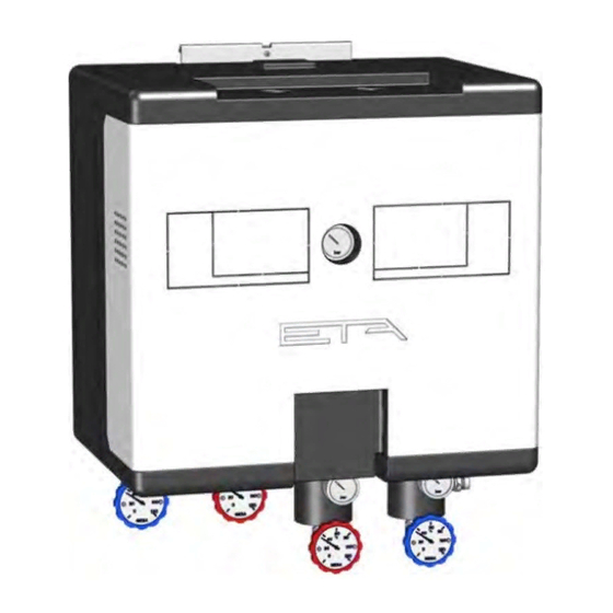
Page 7: Description
Description Description Connections and components Return for primary side and connection for discharge Flow for primary side Flow for secondary side Return for secondary side Primary valve with pressure-independent flow limiter Strainer for secondary side and connection for discharge Actuator for primary valve Strainer for primary side Bleed screw for primary side 10 Safety valve with 3 bar opening pressure... - Page 8 Micro network Radiators with or without buffer stor- 75 °C 43 °C 65 °C 40 °C with ETA boiler age tank Micro network Underfloor heating with mixer and/or 75 °C 36 °C 65 °C 28 °C with ETA boiler...
- Page 9 Description The heat transfer station is controlled via a CAN-bus Mode of operation connection to an existing ETAtouch control system. A The heat supplied by the heat producer reaches the stand-alone solution with a separate ETAtouch control primary valve on the underside of the heat transfer panel is also possible.
-
Page 10: Installation
"Dimensions". Fig. 4-3: Wall mount Fig. 4-1: Front cover Secure the heat transfer station to the wall mount with a screw. Fig. 4-4: Screw Fig. 4-2: Insulation www.eta.co.at... - Page 11 Installation Align the heat transfer station vertically to the wall with Mounting the connections the help of the setting screws. Mount the connections for the primary circuit on the heat transfer station. The return is equipped with an emptying device. Fig.
- Page 12 If no connection is available to the sewage system, the outlet must be directed to the ground in a pipe. Fig. 4-10: Piping led out at the top www.eta.co.at...
- Page 13 Installation A connection for a membrane expansion vessel is Installing the piping available for the secondary side. Connect the piping of the heat producer on the primary side and the piping for the heat consumer on the secondary side. Fig. 4-13: Connection for membrane expansion vessel For frost protection in the secondary circuit, guide the safety valve outlet into a canister DANGER!
-
Page 14: Heat Flow Meter
(blue) connections of the primary circuit. Optionally, a heat meter can be installed in the heat transfer station. This is available separately from ETA. 1. Remove the front cover and switch off the heat transfer station on the mains switch. -
Page 15: Configuration
Configuration Configuration General explanation provided in the additional document A general description for the configuration with the assistant is provided in the document "Control extension - configuration". The configuration of the individual examples is described subsequently. Software version X.44.0 or later The configuration requires software version X.44.0 or later. -
Page 16: Example 1
Hydraulic variants Consumer with its own pump Options: Module is a consumer within an ETA system. Only select this option if the heat transfer module is a consumer in an ETA heating system. This option may not be selected for stand-alone operation (e.g., as district heat-... - Page 17 Configuration Example 1 Circuit Function blocks Description board GM-C 1 Heating circuit Heating circuit Settings: HC type Underfloor heat. Heating circuit pump Standard pump Heating circuit mixing valve 3 point control (230 V) Room sensor Digital GM-C 1 Hot water tank Settings: Charging pump Standard pump...
- Page 18 Example 1 Configuration Terminal assignments If the heat transfer station is a consumer in an ETA heating system, a CAN-bus connection to the ETAtouch control must be established. Description [GM-C 1] Heat transfer station [HOM] Secondary flow S500 T3 Primary valve...
- Page 19 Configuration Example 1...
-
Page 20: Example 2
Hydraulic variants Consumer with its own pump Options: Module is a consumer within an ETA system. Only select this option if the heat transfer module is a consumer in an ETA heating system. This option may not be selected for stand-alone operation (e.g., as district heat-... - Page 21 Output all fault messages Circuit Function blocks Description board EM-C 7 FWM 2pumps ETA fresh water module Connections = type [Heating water] Producers Consumers GM-C 1: HOM: Flow GM-C 1: BufferFlex: . GM-C 1: BufferFlex: Consumer level 1 (top) EM-C 7: FWM: .
- Page 22 Buffer off Sensor 4 From temperature sensor 4 in the buffer, the release for the heating circuit is assigned to the second sensor [Sensor 2]. Thus greater thermal energy is available in the buffer for the fresh water module. www.eta.co.at...
- Page 23 Configuration Example 2 Terminal assignments If the heat transfer station is a consumer in an ETA heating system, a CAN-bus connection to the ETAtouch control must be established. Description [GM-C 1] Heat transfer station [HOM] Secondary flow S500 T3 Primary valve...
-
Page 24: Electrical Connections
ETAtouch control panels of the same type It is impossible to identify circuit boards and ETAtouch control panels when node numbers are assigned more than once. Set the node numbers correctly and conclude by checking them once again. www.eta.co.at... -
Page 25: Can Bus Installation
Electrical connections CAN bus installation CAN bus installation CAN-bus connection to the ETAtouch control system The following example shows the CAN-bus connection from the heat transfer station to the boiler's ETAtouch control. This example applies accordingly to other CAN-bus connections. Fig. -
Page 26: Circuit Board Gm-C3
Secondary flow S500 T4 Temperature input 2 x 0.5 mm² Unassigned S500 T5 Temperature input 2 x 0.5 mm² Primary return S500 T6 Temperature input 2 x 0.5 mm² unassigned S501 T7 Temperature input 2 x 0.5 mm² unassigned www.eta.co.at... - Page 27 Electrical connections Circuit board GM-C3 Minimum Terminal Function cross-sec- Standard assignment tion S501 T8 Temperature input 2 x 0.5 mm² Buffer sensor 1 S501 T9 Temperature input 2 x 0.5 mm² Buffer sensor 2 S501 T10 Temperature input 2 x 0.5 mm² Buffer sensor 3 S501 T11 Temperature input...
-
Page 28: Nt-10Va Circuit Board
Fuse 230 V, T 6,3 A Supply 230 V 3 x 1.5 mm² Mains power input 230 V input Mains switch Supply extension 24 V to circuit board [GM-C]: terminal [S512A] Supply extension 230 V to circuit board [GM-C]: terminal [S1] www.eta.co.at... -
Page 29: Heat Flow Meter
Electrical connections Heat flow meter Heat flow meter Connect the heat meter electrically Connect the heat meter to the board [GM-C]. See the following graphic. The M-Bus circuit board shown is optionally available and only required when the heat meter is to be evaluated by the ETAtouch control system. Fig. -
Page 30: Commissioning
Proper use includes compliance with these instruc- tions as well as the information and labelling on the pump. Filling and bleeding the heating system Fill the heating system and take note of the maximum water pressure. Carefully bleed the heating system after filling. www.eta.co.at... -
Page 31: Setting The Flow Rate
Commissioning Setting the flow rate Setting the flow rate 7.2.1 Primary side characteristic curve Primary side characteristic curves Using the table, a primary side spread of 30 K results for the secondary side radiator heating (18 kW, 20 K spread). At 18 kW power and 30 K spread a primary side flow rate of approx. -
Page 32: Determination Of Volume Flow
2. Remove the safety ring for the setting. Fig. 7-3: Safety ring 3. Close the restrictor (knurled screw with recess for positioning) completely by turning clockwise. Fig. 7-1: Adjusting diagram Fig. 7-4: Restrictor Adapting the flow rate with the restrictor is described in the following. www.eta.co.at... -
Page 33: Example Calculation
Commissioning Setting the flow rate 4. Reopen the restrictor counterclockwise by the 7.2.3 Example calculation required number of rotations ("U"). Example with two heating circuits A building with two heating circuits should be supplied by way of a heat transfer station. Total heat output is 18 kW. -
Page 34: Concluding Activities
15 must be opened by 3.5 rotations. Concluding activities Refitting the insulation Refit the front cover and all the insulation of the heat transfer station previously removed. Also reattach the insulation for the primary connections (flow, return). www.eta.co.at... -
Page 35: Rectifying Problems
Rectifying problems Rectifying problems 4. Clean the strainer and then reinsert it. Cleaning the strainer If the performance of the heat transfer station decreases during operation, often the strainer is dirty. Therefore, clean the strainer first before carrying out other measures. The strainers are located on the primary and secondary side. - Page 36 Rectifying problems 7. Bleeding the corresponding circuit is required after cleaning. There is a bleed screw on the top for bleeding the primary side. Fig. 8-4: Bleeding the primary side 8. Reattach the front cover www.eta.co.at...
-
Page 37: Water Hardness
Water hardness Water hardness Determine permissible water hardness for the heating water according to ÖNORM H 5195-1 Table 1 Table 2 Heat producer with large (> 0.3 l/ Heat producer with small (≤ 0.3 l/ kW) water content kW) water content Specific water content ≥... -
Page 38: 10 Etatouch Controller
Inputs The consumers, for example a heating circuit and a hot Heat meter water tank, are supplied with heat from the separately Read out interval regulated pump and the changeover valve on the heat transfer station. www.eta.co.at... -
Page 39: Software Update
5. After installation, a prompt appears to remove the You can find the files required for the software update USB -memory stick. in the login area of the www.ETA.co.at website, and After removing the USB stick, the ETAtouch control also on www.meinETA.at. - Page 40 DOWNLOAD www.eta.co.at...
Need help?
Do you have a question about the 939058-001 and is the answer not in the manual?
Questions and answers