Table of Contents
Advertisement
Quick Links
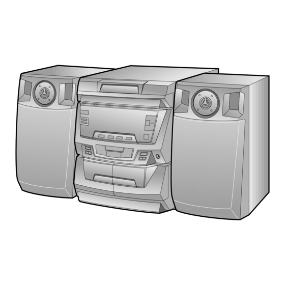
Illustration: CD-C405W/CP-C405
Illustration: CD-C420H/CP-C410/CP-SR401
SPECIFICATIONS ............................................................................................................................................................. 2
VOLTAGE SELECTION (CD-C405W ONLY) .................................................................................................................... 2
NAMES OF PARTS ........................................................................................................................................................... 3
OPERATION MANUAL ...................................................................................................................................................... 5
DISASSEMBLY .................................................................................................................................................................. 6
REMOVING AND REINSTALLING THE MAIN PARTS ..................................................................................................... 9
ADJUSTMENT .................................................................................................................................................................. 10
NOTES ON SCHEMATIC DIAGRAM ............................................................................................................................... 12
BLOCK DIAGRAM ............................................................................................................................................................ 13
SCHEMATIC DIAGRAM / WIRING SIDE OF P.W.BOARD .............................................................................................. 16
WAVEFORMS OF CD CIRCUIT ....................................................................................................................................... 30
TROUBLESHOOTING (CD CHANGER CONTROL / CD SECTION) ............................................................................... 31
FUNCTION TABLE OF IC ................................................................................................................................................ 35
FL DISPLAY ...................................................................................................................................................................... 41
REPLACEMENT PARTS LIST/EXPLODED VIEW
All manuals and user guides at all-guides.com
CD-C405W/CD-C420H/CP-C410/CP-C405/CP-SR421
SERVICE MANUAL
CONTENTS
SHARP CORPORATION
- 1 -
CD-C405W
CD-C420H
CP-C405
CP-C410
CP-SR421
CD-C405W and CP-C405 constitute CD-C405W.
CD-C420H and CP-C410 and CP-SR421 constitute CD-
C405W.
• In the interests of user-safety the set should be restored to its
original condition and only parts identical to those specified be
used.
No. S5733CDC405W/
Page
Advertisement
Table of Contents

Related Manuals for Sharp CD-C405W


Summary of Contents for Sharp CD-C405W
-
Page 1: Table Of Contents
CONTENTS Page SPECIFICATIONS ................................2 VOLTAGE SELECTION (CD-C405W ONLY) ........................2 NAMES OF PARTS ................................3 OPERATION MANUAL ..............................5 DISASSEMBLY .................................. 6 REMOVING AND REINSTALLING THE MAIN PARTS ..................... 9 ADJUSTMENT .................................. -
Page 2: Specifications
Wow and flutter: 0.15 % (WRMS) VOLTAGE SELECTION (CD-C405W) Before operating the unit on mains, check the preset voltage. If the votage is different from your local voltage. Slide the AC power supply socket cover by slightly loosing the screw to the visible indication of the side of your local voltage. -
Page 3: Names Of Parts
All manuals and user guides at all-guides.com CD-C405W/CD-C420H/CP-C410/CP-C405/CP-SR421 NAMES OF PARTS CD-C405W/CD-C420H Front Panel 1. Disc Tray 3 4 5 2. Disc Number Indicator 3. Timer Indicator 4. Record Indicator SLEEP X-BASS 5. Sleep Indicator 6. Extra Bass Indicator: X-BASS 8 9 10 7. - Page 4 All manuals and user guides at all-guides.com CD-C405W/CD-C420H/CP-C410/CP-C405/CP-SR421 CD-C420H Rear Panel 1. Speaker Terminals 2. AC Power Lead 3. Video/Auxiliary (Audio Signal) Input Sockets 4. FM 75 Ohms Aerial Socket 5. AM Loop Aerial Socket CP-C410 Speaker Section 6. Full Range Speaker 7.
-
Page 5: Operation Manual
All manuals and user guides at all-guides.com CD-C405W/CD-C420H/CP-C410/CP-C405/CP-SR421 OPERATION MANUAL – 5 –... -
Page 6: Disassembly
All manuals and user guides at all-guides.com CD-C405W/CD-C420H/CP-C410/CP-C405/CP-SR421 DISASSEMBLY CD-C405W/CD-C420H Caution on Disassembly Illustration: CD-C405W Follow the below-mentioned notes when disassembling the unit and reassembling it, to keep it safe and ensure Top Cabinet ( A1 ) x2 excellent performance: ø3 x12mm... - Page 7 All manuals and user guides at all-guides.com CD-C405W/CD-C420H/CP-C410/CP-C405/CP-SR421 ( K1 ) x4 ( E1 ) x9 ø3 x14mm Front Panel ø3 x8mm ( L1 ) x1 ø2.6 x10mm ( E1 ) x1 ø3 x8mm Display PWB Shift Lever ( E2 ) x2...
- Page 8 All manuals and user guides at all-guides.com CD-C405W/CD-C420H/CP-C410/CP-C405/CP-SR421 CP-SR421 CP-C405 Front Panel (C1) x1 Woofer Speaker Box Screw driver (B1)x2 Driver should be pried ø3x20mm away from speaker Box. (B1)x2 (B1)x2 ø3x20mm Direction of handle ø3x20mm Figure 8-2 Figure 8-1...
-
Page 9: Removing And Reinstalling The Main Parts
All manuals and user guides at all-guides.com CD-C405W/CD-C420H/CP-C410/CP-C405/CP-SR421 REMOVING AND REINSTALLING THE MAIN PARTS CD MECHANISM SECTION Perform steps 1, 2, 3, 10 and 11 of the disassembly method Loading Motor to remove the CD mechanism. How to remove the loading motor (See Fig. -
Page 10: Adjustment
• Driving Force Check fL: Low-range frequency fH: High-renge frequency Torque Meter Specified Value • AM IF/RF (CD-C405W) Play: TW-2412 Tape 1: Over 80 g Signal generator: 400 Hz, 30%, AM modulated Tape 2: Over 80 g Test Stage Frequency... - Page 11 All manuals and user guides at all-guides.com CD-C405W/CD-C420H/CP-C410/CP-C405/CP-SR421 TEST MODE • Setting the test mode Any one of test mode can be set by pressing several keys as follows. <REC. PAUSE> + <DISC. SKIP> + <POWER> TEST: CD operation test •...
-
Page 12: Notes On Schematic Diagram
ON—OFF SW717 POWER ON—OFF DISC NUMBER ON—OFF SW718 CLOCK ON—OFF PICKUP IN ON—OFF SW719 TIMER/SLEEP ON—OFF SW301 SPAN SELECTOR 50/9-100/10 [CD-C405W ONLY] SW721 MEMORY/SET ON—OFF SW701 RANDOM/DEMO ON—OFF SW722 ON—OFF SW702 VOLUME DOWN ON—OFF SW723 TUNER ON—OFF SW703 X-BASS ON—OFF... -
Page 13: Block Diagram
All manuals and user guides at all-guides.com CD-C405W/CD-C420H/CP-C410/CP-C405/CP-SR421 Figure 13 BLOCK DIAGRAM (1/3) – 13 –... - Page 14 All manuals and user guides at all-guides.com CD-C405W/CD-C420H/CP-C410/CP-C405/CP-SR421 420H ONLY 420H ONLY 420H ONLY SO301 FM IF FE301 AM IF ANTENNA FM FRONT END CF302 L354 CF301 Q301 TERMINAL T351 420H: S0003AW MONO/ FM IF IN 405W: S0005AW FM/AM ANTENNA...
- Page 15 All manuals and user guides at all-guides.com CD-C405W/CD-C420H/CP-C410/CP-C405/CP-SR421 UNSWITCH FL701 DISPLAY MEMORY BACK UP MONO/ST 31 32 TO CD SECTION TO CD SECTION Q701 TO POWER SECTION L-CH R-CH PHM1 MUTING Q353 Q354 SW701 AVDD SW725 IC701 AVREF IX0191AW XL702 SYSTEM CONTROL 4.19MHz...
-
Page 16: Schematic Diagram / Wiring Side Of P.w.board
All manuals and user guides at all-guides.com CD-C405W/CD-C420H/CP-C410/CP-C405/CP-SR421 P19 7-H TO SENSOR PWB CNS10 SW717 POWER 10 9 8 7 6 5 4 3 2 1 SW718 10 15 CLOCK R769 CNP10 R765 SW715 TIMER/SLEEP TUN-DOWN SW719 SW721 MEMORY/SET TO TAPE MECHANISM PWB... - Page 17 All manuals and user guides at all-guides.com CD-C405W/CD-C420H/CP-C410/CP-C405/CP-SR421 P18 5-D P18 4-D P18 5-H P19 9-C TO CD MOTOR PWB TO PICKUP UNIT TO PICKUP UNIT TO TUNER PWB CNS3A CNS2A CNS1A CNP303 MAIN PWB-A1 6 5 4 3 2...
- Page 18 All manuals and user guides at all-guides.com CD-C405W/CD-C420H/CP-C410/CP-C405/CP-SR421 P16 1-B TO DISPLAY PWB PICKUP UNIT CNSM1 CNS1B 1 2 3 4 5 1 2 3 4 5 6 7 8 CNS2B 405W ONLY 1 2 3 4 5 1 2 3 4 5 6 7 8...
- Page 19 All manuals and user guides at all-guides.com CD-C405W/CD-C420H/CP-C410/CP-C405/CP-SR421 TUNER PWB-B1 POWER PWB-B2 F963 T1.6A L 250V CNS901 F962 T2.5A L 250V TO MAIN PWB CNP901 P17 11-G T961 POWER TRANSFOMER Q354 E C B Q353 R367 E C B C374...
Need help?
Do you have a question about the CD-C405W and is the answer not in the manual?
Questions and answers