
Related Manuals for Heinrichs TMU


Summary of Contents for Heinrichs TMU
- Page 1 Coriolis Mass Flow Meter Generation Installation and operation manual with UMC3 Please read the instructions carefully and store them in a safe place Heinrichs Messtechnik GmbH OPERATING MANUAL TMU / UMC3 May 2021...
-
Page 2: Table Of Contents
Construction details ..........................24 Dimensions and weight ........................... 24 Dimensions of the sensor types TMU 006 to TMU 050 ................26 Dimensions of the sensor types TMU 080 to TMU 300 ................28 Dimension drawings for sensors with heating ..................31 Material .............................. - Page 3 OPERATION ........................... 50 Control unit BE4 ............................50 Introduction ............................50 Operating modes ............................. 51 Operator interface ..........................51 The keys and their functions ........................52 Functional classes, functions and parameters ..................53 OPERATING MANUAL TMU / UMC3 Page 3 of 122...
- Page 4 Standard operating mode ........................113 Custody transfer mode .......................... 113 List of error messages ........................... 113 Returning the Meter ..........................117 Declaration of Decontamination ......................118 DECLARATION OF CONFORMITY ..................119 Page 4 of 122 OPERATING MANUAL TMU / UMC3...
-
Page 5: Introduction
8.3, “Returning the Meter” before returning the device to Heinrichs Messtechnik. The operator is liable for any substance removal or personal damage costs arising from inadequate cleaning of a device sent for repair. -
Page 6: Identification
Email: info@heinrichs.eu Product type: Mass flow-rate meter for liquid and gaseous products Product name: Sensor type: 2nd Generation Transmitter type: UMC3 File name: tmu_umc3_ba_21.02_en.docx Version:. 21.02, dated, 19 May 2021 Page 6 of 122 OPERATING MANUAL TMU / UMC3... -
Page 7: Steps Prior To Operation
Heinrichs Messtechnik GmbH extends no express or implied warranty concerning the applicability of the present document for any purpose other than that described. -
Page 8: Safety Advisory For The User
We advice always to abide to these instructions! Note means that the accompanying text contains important information about the product, handling the product or about a section of the documentation that is of particular importance. Page 8 of 122 OPERATING MANUAL TMU / UMC3... -
Page 9: Proper Use Of The Device
Only original replacement parts are to be used. Heinrichs Messtechnik GmbH accepts no liability for any loss or damage of any kind arising from improper operation of any product, improper handling or use of any replacement part, or from external electrical or mechanical effects, overvoltage or lightning. -
Page 10: Returning Your Flowmeter For Servicing Or Calibration
This is particularly important for the explosion-proof transmitter. The specified precision of the electronics is only guaranteed if the complete stack is replaced. Page 10 of 122 OPERATING MANUAL TMU / UMC3... -
Page 11: Maintenance
In the event of a tube rupture, e.g. due to corrosion or damage, medium will leak into and fill the enclosures body, which can lead to subsequent damage to the external housing, particularly at high process pressures! OPERATING MANUAL TMU / UMC3 Page 11 of 122... -
Page 12: The Tmu Sensor
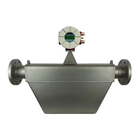
3. The TMU sensor Application domain of the TMU sensor The TMU sensor is intended for use solely for direct and continuous mass flow measurement of liquids and gases, irrespective of their conductivity, density, temperature, pressure, or viscosity. The sensor can be utilised for the direct and continuous mass flow measurement of chemical fluids, suspensions, molasses, paint, varnish, lacquer, pastes and similar materials. -
Page 13: Performance Characteristics Of The Tmu Sensor
Heinrichs Messtechnik GmbH Performance characteristics of the TMU sensor Reference conditions Established flow profile Inlet section has to correspond to mounting length Control valves always positioned downstream Measurement is to be performed with a liquid containing no gas bubbles ... -
Page 14: Density Measurement
2 g/l TMU-x100 5 g/l 2 g/l TMU-x150 5 g/l 2 g/l TMU-x200 5 g/l 2 g/l TMU-x250 5 g/l 2 g/l TMU-x300 5 g/l 2 g/l Table 2: Density accuracy Page 14 of 122 OPERATING MANUAL TMU / UMC3... -
Page 15: Accuracy
Influence of fluid temperature Compensated Influence of fluid pressure For fluids: too small to be relevant (1) Refer to section 3.3.2, “TMU flow ranges” for detailed information on flow ranges. Table 3: Measurement Deviation OPERATING MANUAL TMU / UMC3 Page 15 of 122... -
Page 16: Pressure Loss Tmu
1,30 bar 14697,2 lbs/min 31231,6 lbs/min 47766,0 lbs/min 64300,4 lbs/min 80834,8 lbs/min TMU-x300 14697,2 lbs/min 80834,8 lbs/min 0,05 bar 0,20 bar 0,47 bar 0,85 bar 1,34 bar Table 4: Pressure losses Page 16 of 122 OPERATING MANUAL TMU / UMC3... -
Page 17: Environmental Conditions
In conformity with IEC 654-1. Unsheltered class D locations with direct open-air climate. Ingress protection Sensor: IP 67 (NEMA 6), Transmitter: IP68 / 1 m for 24 hours (NEMA 6P) acc. to DIN EN 60529 with mounted and sufficiently tightened approved cable glands. OPERATING MANUAL TMU / UMC3 Page 17 of 122... -
Page 18: Operating Conditions
The sensor is not to be used to support a pipe or other pipe components. Do not install the sensor in suspended pipes. Do not adjust the position of a pipe by pulling or grasping the sensor. Page 18 of 122 OPERATING MANUAL TMU / UMC3... -
Page 19: Installation Orientation
Heinrichs Messtechnik GmbH Installation Orientation Without compromising its accuracy, the TMU can be installed and operated in various orientations. The following representations show the most common installation positions and provide tips on how the operator can prevent installation-related influences on the measurement. - Page 20 Flow direction should be from top to bottom so that any forming gas/liquid, position condensate that forms can flow out efficiently moisture Position A Position B Condensate might form in flowmeter Position C Not recommended owing to condensate accumulation in flowmeter Page 20 of 122 OPERATING MANUAL TMU / UMC3...
-
Page 21: Pressure Surges
Using the device with hazardous fluids The sealing technology used for the standard TMU mass flowmeter renders the device unsuitable for use with hazardous fluids. Only sensors that meet the standards for safety instruments and which are declared as such are suitable for use with hazardous fluids. -
Page 22: Vibration Stability
A rule of thumb in this regard is as follows: A 1 % gas component will increase false readings by 1 %. The gas component is not to exceed 5 %. Page 22 of 122 OPERATING MANUAL TMU / UMC3... -
Page 23: Process Pressure Range
If the transmitter is not mounted directly on the sensor, installation regulations and applicable legal standards are to be adhered to. The maximum cable length is 200 m (approx. 650 ft). See Section 5.1.3 on page 46 for information regarding the connection and cable specifications. OPERATING MANUAL TMU / UMC3 Page 23 of 122... -
Page 24: Construction Details
1788 [70,4] 1890 [74,4] 1990 [78,3] 1300 [51,2] 550 [21,7] TMU-x300 1896 [74,6] 1998 [78,7] 1793 [70,6] 1895 [74,6] 1995 [78,5] 1400 [55,1] 510 [20,1] Table 7: Process temperature dependant dimensions Page 24 of 122 OPERATING MANUAL TMU / UMC3... - Page 25 Table 9: Sensor Weights In the sensor weights stated in Table 9, the flanges are not considered. The overall weight can only be stated once the sensor has been conclusively configured. OPERATING MANUAL TMU / UMC3 Page 25 of 122...
-
Page 26: Dimensions Of The Sensor Types Tmu 006 To Tmu 050
Heinrichs Messtechnik GmbH Dimensions of the sensor types TMU 006 to TMU 050 Dimension drawings of the Standard version Integral mount configuration that is suitable for process temperatures up to 100 °C (212°F): For all the dimensions and weight, see Section 3.5.1 Dimensions and weight on page 24. - Page 27 Remote mount configuration with junction box that is suitable for process temperatures up to 180 °C (356 °F): For all the dimensions and weights, see Section 3.5.1 Dimensions and weight on page 24. OPERATING MANUAL TMU / UMC3 Page 27 of 122...
-
Page 28: Dimensions Of The Sensor Types Tmu 080 To Tmu 300
Remote mount configuration with junction box that is suitable for process temperatures up to 260 °C (500 °F): For all the dimensions and weights, see Section 3.5.1 Dimensions and weight on page 24. Dimensions of the sensor types TMU 080 to TMU 300 Dimension drawings of the Standard version Integral mount configuration that is suitable for process temperatures up to 100 °C (212 °C):... - Page 29 Remote mount configuration (with junction box) that is suitable for process temperature up to 100 °C (212 °F): For all the dimensions and weights, see Section 3.5.1 Dimensions and weight on page 24. Remote mount version dimension drawing up to 180 °C (356°F) OPERATING MANUAL TMU / UMC3 Page 29 of 122...
- Page 30 Remote mount configuration (with junction box) that is suitable for process temperatures up 260 °C (500 °F): For all the dimensions and weights, see Section 3.5.1 Dimensions and weight on page 24. Page 30 of 122 OPERATING MANUAL TMU / UMC3...
-
Page 31: Dimension Drawings For Sensors With Heating
Heinrichs Messtechnik GmbH Dimension drawings for sensors with heating Sensor types TMU 008 to TMU 050 Additional heater dimensions: For all the dimensions and weights, see Section 3.5.1 Dimensions and weight on page 24. Sensor types TMU 080 to TMU 300 Additional heater dimensions: For all the dimensions and weights, see Section 3.5.1 Dimensions and weight on page 24. -
Page 32: Material
1.4301 (304L) Flow tubes: 1.4404 (316Ti), Hastelloy or Tantalum Splitter: 1.4571 (316Ti) or Hastelloy Flange Connectors: 1.4571 (316Ti) or Hastelloy (with Tantalum sealing surface by Tantalum flow tubes) Other materials on request Page 32 of 122 OPERATING MANUAL TMU / UMC3... -
Page 33: Umc3 Transmitter
4. UMC3 transmitter Application domain of the UMC3 transmitter The UMC3 transmitter (hereinafter referred to as UMC3) for use with TM, TME TMR, TMU, TM-SH and HPC Coriolis mass-flow sensors, is a programmable transmitter designed to captured and processes measurement data from its associated sensor for displaying on its built in display or for the transmission of measurement results via various interfaces. -
Page 34: Operating Conditions
Warning: Adapters mounted by the manufacturer may never be removed by the customer! In the event of a removal of these adapters, the protection class Ex-d can no longer be guaranteed. Page 34 of 122 OPERATING MANUAL TMU / UMC3... -
Page 35: Environmental Conditions
Electromagnetic compatibility can be guaranteed only if the lids of the enclosure are securely tightened. Leaving the enclosure open may lead to electromagnetic disturbances. Warning In Ex hazardous areas, only sensors and transmitters marked as such on their rating plates may be used! OPERATING MANUAL TMU / UMC3 Page 35 of 122... -
Page 36: Process Conditions
The highly integrated electronic components may be damaged when exposed to ESD hazards. Only when installed in the transmitters enclosure are the electronics compliant to EMC standards. Page 36 of 122 OPERATING MANUAL TMU / UMC3... -
Page 37: Input Measured Variables
Measured Values The UMC measures via the connected sensor the following variables: mass flow rate, temperature, density Note: Density and volume variables are not available for all sensor types. OPERATING MANUAL TMU / UMC3 Page 37 of 122... -
Page 38: Measuring Range
The measuring range, which varies according to the used sensor, can be found in the relevant data sheet and in sections 3.3.2, “TMU flow ranges” and 3.3.3, “Density measurement” on page 14. The specified measuring range of the delivered sensor is also printed on the devices rating plate. -
Page 39: Current Outputs
Maximal error of the current outputs is ±0.1 % of the actual reading + 0.05 % full scale flow. 4.8.2.2 Load Standard version: 500 ohms Explosion-proof version: 500 ohms HART minimum load: 250 ohms OPERATING MANUAL TMU / UMC3 Page 39 of 122... - Page 40 If the measured value is lower than the set cut-off, the flow rate will be set to 0.0 (kg/h). This results in the analogue output being set to 0/4 mA, and the pulse output will cease generating pulses. Page 40 of 122 OPERATING MANUAL TMU / UMC3...
-
Page 41: Construction Details Umc3
Construction details UMC3 The UMC3 with the SG1 field enclosure possesses a variety of mounting options, making it adaptable to available local circumstances. Mounting / Dimensions Horizontal pipe mounting Vertical pipe mounting OPERATING MANUAL TMU / UMC3 Page 41 of 122... -
Page 42: Weight
4.5 kg (9.9 lbs) (remote UMC3 transmitter) Material Enclosure: GK Al Si 12 MG wa, vor der Lackierung chromatisiert Chemically resistant paint. Mounting bracket: 2 mm thick sheet stainless steel / (6 mm with ships approval) Page 42 of 122 OPERATING MANUAL TMU / UMC3... -
Page 43: Electrical Connections Umc3
(Non Ex) UMC3 L, N and PE Table 11: Power Terminals Designation On DC Voltage devices, L represents the “ ” and N the “ “ of the supply lines. Netzanschlussklemmen UMC3 OPERATING MANUAL TMU / UMC3 Page 43 of 122... -
Page 44: The Output Terminals
33(-) and 34(+) (Status for Custody transfer) 53(-) and 54(+) Option Profibus PA 39 (A) and 40 (B) Control unit BE (connector) Shield, -, + Table 12: Signal Output Terminals Designation Page 44 of 122 OPERATING MANUAL TMU / UMC3... - Page 45 Field bus devices (Profibus PA or FF) are not outfitted with analog or impulse outputs. Control unit connector and communication interface terminals Signal output terminals Output Signals shown in Ex-ia type of protection OPERATING MANUAL TMU / UMC3 Page 45 of 122...
-
Page 46: Sensor Connection
Attention: Cables not certified by the manufacturer may impair the accuracy of the measurement as well as EMC compliance. Suitable alternative cables: SLI2Y (ST) C11YÖ 5 x 2 x 0.5 mm or SG [5(2 LiY 0.50)St]FStC11Y Page 46 of 122 OPERATING MANUAL TMU / UMC3... - Page 47 The colours of the sensor’s wires in the terminal box may differ to the colours of the connection cable wires! Decisive for the connection is the numbers of the terminal in the terminal box and transmitter. OPERATING MANUAL TMU / UMC3 Page 47 of 122...
- Page 48 Heinrichs Messtechnik GmbH UMC3 connection to the sensor For terminal assignment refer to section 5.1.3 “Sensor connection“ For advice on cable glands: See also 4.5.1, “Installation conditions and cable glands” on page 34. Page 48 of 122 OPERATING MANUAL TMU / UMC3...
-
Page 49: Certificates And Approvals
Table 15: Certifications Explosion Protection Type Approval certificates are available on our website www.heinrichs.eu, or upon request. Custody transfer applications The Combination UMC3/TMU possess an EU-Type certification according to the OIML Scheme for conformance to the following recommendations: Certificate numbers OIML... -
Page 50: Operation
At temperatures below − 10 C° (14 °F), only static values (parameter settings) can be displayed. At temperatures exceeding 60 C° (140 °F), contrast decreases substantially on the LCD and the liquid crystals can dry out. Page 50 of 122 OPERATING MANUAL TMU / UMC3... -
Page 51: Operating Modes
Menu level subpoint all sub-menus that are assigned to a functional class Selection Function [no] are displayed beneath the Function value selected ___________ value selected from list relevant class. from list OPERATING MANUAL TMU / UMC3 Page 51 of 122... -
Page 52: The Keys And Their Functions
ENTER key: Pressing the ““-key moves you from the menu level to the selected Sub-menu parameter level. - All entries are acknowledged with the key. Image 3: BE2 Control unit Push-button description Page 52 of 122 OPERATING MANUAL TMU / UMC3... -
Page 53: Functional Classes, Functions And Parameters
(see 7.1.5.3, “Passwords” on page 54), the operator can navigate to the desired setting by using the key or the key and the operator can then confirm your selection by pressing “ “. To retain the current setting, press “Esc”. OPERATING MANUAL TMU / UMC3 Page 53 of 122... - Page 54 The service password allows for modification of all UMC3 functions. This password is not given to customers. For further information on customer passwords, see Section 7.2.2, “PASSWORD functional class” on page Page 54 of 122 OPERATING MANUAL TMU / UMC3...
-
Page 55: Umc3 Transmitter Functional Classes
In the following, all software functions that can be accessed using the customer password are described. Functions that are only accessible to the vendor (service functions) are not described in the present document. OPERATING MANUAL TMU / UMC3 Page 55 of 122... -
Page 56: Measured Values Functional Class
Display mode Counter R Density d h min start -up Temperature QM + Counter F QM + Density QM + temperature QV + Counter F QV + Density Raw values Raw values Page 56 of 122 OPERATING MANUAL TMU / UMC3... - Page 57 After selecting the Counter reverse function, the current reading of the reverse flow counter will be displayed: Counter reverse XXXXXXXX.XX kg The operator can define the display unit in the COUNTERS functional class using the Unit of counters function. OPERATING MANUAL TMU / UMC3 Page 57 of 122...
- Page 58 The second line shows the value of the counter forward. The operator can define the display unit in the FLOW functional class using the Mass flow QM unit function and the counter unit using the Unit of counters function in the COUNTERS functional class. Page 58 of 122 OPERATING MANUAL TMU / UMC3...
- Page 59 The operator can define the display unit in the FLOW functional class using the Volume flow QM unit function and the unit for density measurement in the DENSITY functional class using the Density unit function. OPERATING MANUAL TMU / UMC3 Page 59 of 122...
- Page 60 Measure for the phase displacement between the sensor signals. ttt.ttt: Indicates the measured sensor temperature. fff.ffff: Indicates the current oscillation frequency of the system. eee.aaa: Indicates the value of the excitation current (eee) and the sensor voltage (aaa). Page 60 of 122 OPERATING MANUAL TMU / UMC3...
-
Page 61: Password Functional Class
0000 The numbers 0000 are displayed and can be changed by toggling the arrow keys as description in section 7.1.5.2, “Input window/modify a value”. Pressing the ““- key verifies the password. OPERATING MANUAL TMU / UMC3 Page 61 of 122... - Page 62 You do not need the service password for setting the functions necessary for operation. The service password is reserved for service technicians and not provided to customers. Correct settings are essential for proper operation of the device (e.g. parameterization and calibration values). Page 62 of 122 OPERATING MANUAL TMU / UMC3...
-
Page 63: Counter Functional Class
Reset counters ? [no] Reset ________________ counters To change the current settings, enter the customer password. Otherwise, the settings can only be displayed but not changed. To cancel the current action, press “Esc”. OPERATING MANUAL TMU / UMC3 Page 63 of 122... - Page 64 (0.00). Reset counters [no] By pressing “Esc” or toggling to [no] the operator can cancel the current action without changing the counter readings. Pressing the “” key confirms the selection. Page 64 of 122 OPERATING MANUAL TMU / UMC3...
-
Page 65: Measurement Processing Functional Class
Damping 03 s Low flow cut-off Low flow cut-off 01 % Low flow cut -off Low flow cut -off hysteresis Hysteresis 01 % x.xxx kg/h cal. ? [no] Zeropoint _________________ calibration OPERATING MANUAL TMU / UMC3 Page 65 of 122... - Page 66 Low flow cut-off hysteresis function and pressing “ “, the following selection field will be displayed: Low flow cut-off Hysteresis 00 % The current hysteresis will be displayed and can be changed by toggling the arrow keys. Pressing the “” key confirms the entry. Page 66 of 122 OPERATING MANUAL TMU / UMC3...
- Page 67 ? [no] The operator can toggle between [yes] and [no]. Entering [yes] initiates a new zero point calibration. After setting the new value, press “ “ to confirm your entry. OPERATING MANUAL TMU / UMC3 Page 67 of 122...
-
Page 68: Flow Functional Class
QM limit MIN MIN = 10 % prog. unit Mass flow Mass flow limit Volume flow QV Range = 100 % QM limit MAX MAX = 90 % QV range 0120.00 l/h Page 68 of 122 OPERATING MANUAL TMU / UMC3... - Page 69 F = 001.0 kg The factor always refers to the unity of kg. A new factor can be entered by toggling the arrow keys. Pressing the “” key confirms the entry. OPERATING MANUAL TMU / UMC3 Page 69 of 122...
- Page 70 MAX = 90 % The current MAX flow limit value for mass flow will be displayed and can be changed by toggling the arrow keys. Pressing the “” key confirms the entry. Page 70 of 122 OPERATING MANUAL TMU / UMC3...
- Page 71 A conversion factor can be entered as a substitute for a not available mass flow unit as described in the after- following chapter 7.2.5.8, “Factor volume flow QV programmable unit” on page 72. In this case the unity xx is selected into combination with the desired time unit. OPERATING MANUAL TMU / UMC3 Page 71 of 122...
- Page 72 The current upper-range value for volume flow will be displayed and can be changed by toggling the arrow keys. Pressing the “” key confirms the entry. Output and display of the measured value is only possible for mass flowmeters for which received a density calibration. Page 72 of 122 OPERATING MANUAL TMU / UMC3...
-
Page 73: Density Functional Class
Measured. Values 060.50°C 166.409 Hz limit MAX MAX = 1200.0 g/l hot medium Rho= 0994.1 g/l Calculate? [no] Density limit Density limit Finish calibration ______________ hysteresis Hyst.= 000.5 g/l of density OPERATING MANUAL TMU / UMC3 Page 73 of 122... - Page 74 Press “” to confirm and apply the selection. A conversion factor can be entered as a substitute for a not available density as described in the after-following section 7.2.6.3, “Factor programmable density unit” on page 75. Page 74 of 122 OPERATING MANUAL TMU / UMC3...
- Page 75 After selecting the Density upper-range value function, press “” to display the following selection field: Density 100 % = XXXXX g/l The current upper-range value will be displayed and can be changed by toggling the arrow keys. Pressing the “” key confirms the entry. OPERATING MANUAL TMU / UMC3 Page 75 of 122...
- Page 76 After selecting the Density limit hysteresis function, press “” to display the following selection field: Density limit Hysteresis 000.0 g/l The current limit hysteresis value will be displayed and can be changed by toggling the arrow keys. Pressing the “” key confirms the entry. Page 76 of 122 OPERATING MANUAL TMU / UMC3...
- Page 77 [Process density] The current operating mode for density measurement will be displayed and can be changed between the two modes by toggling the arrow keys. Pressing the “” key confirms the entry. OPERATING MANUAL TMU / UMC3 Page 77 of 122...
- Page 78 In this software version, it will not be used for calculations. operat. pressure 001.00 bar The current value process pressure will be displayed in bar and can be changed by toggling the arrow keys. Pressing the “” key confirms the entry. Page 78 of 122 OPERATING MANUAL TMU / UMC3...
- Page 79 The reference values for the density measurement are then calculated and saved. Furthermore, to activate density measurement the density measurement must be activated as described in section 7.2.6.1, “Density measurement on/off” on page 74. OPERATING MANUAL TMU / UMC3 Page 79 of 122...
-
Page 80: Temperature Functional Class
Temperature Temperature upper range val. 100% = + 100 °C Temperature limit MIN. temperature - 050 °C Temperature limit MAX. temperature +250 °C Max. measured permissible +250 °C temperature measured +197°C Page 80 of 122 OPERATING MANUAL TMU / UMC3... - Page 81 100 % = +090 °C The current upper-range value for temperature measurement will be displayed and can be changed by toggling the arrow keys. Pressing the “” key confirms the entry. OPERATING MANUAL TMU / UMC3 Page 81 of 122...
- Page 82 After selecting this display, the largest measured temperature will be displayed. For comparison, the set maximum limiting value will be displayed in the first line. permissible +250 °C measured +197 °C This value cannot be reset since it stores the maximum measured process temperature. Page 82 of 122 OPERATING MANUAL TMU / UMC3...
-
Page 83: Pulse Output Functional Class
______________ m³ cm³ Pulse output unit ston lton ft³ acft flox xxQM xxQV 1 pulse per [1.0] unit ________________ 0.001 Pulse value 0.01 10.0 100.0 Pulse width Pulse width 0050.0 ms OPERATING MANUAL TMU / UMC3 Page 83 of 122... - Page 84 The valency of the programmable units are defined by the settings of the flow units described in sections 7.2.5.2, “Factor mass flow QM programmable unit” on page 69 and 7.2.5.8, “Factor volume flow QV programmable unit” on page 72. Page 84 of 122 OPERATING MANUAL TMU / UMC3...
- Page 85 The maximum output frequency can be calculated using the following formula: 1000 pulse width If connecting to electrical counter relays, we recommend pulse widths greater than 4 ms; for electromechanical counter relays the preset value should be 50 ms. OPERATING MANUAL TMU / UMC3 Page 85 of 122...
-
Page 86: Status Functional Class
MAX QM MIN density MAX density Alarm not avail. only custody transfer Input assig. to no standard [not avail.] ________________ Binary input counter = 0! assignment set zero! clr. errors not avail. Page 86 of 122 OPERATING MANUAL TMU / UMC3... - Page 87 Pressing the “” key confirms the entry. When selecting the IMP2 90° setting, a second pulse output will be realised via the status output that can be used for custody transfer operations. OPERATING MANUAL TMU / UMC3 Page 87 of 122...
- Page 88 Pressing the button for a short moment: display test Pressing the button for more than 5 seconds: error reset Input assigned to: [[Reset error] The push-button may be assigned other functions for non-custody transfer operations. Page 88 of 122 OPERATING MANUAL TMU / UMC3...
- Page 89 Standard setting: Not available Others: Counters = 0, i.e. reset counters to zero. Zero point, i.e. carry out zero point calibration Reset error, i.e. acknowledge error messages OPERATING MANUAL TMU / UMC3 Page 89 of 122...
-
Page 90: Current Outputs Functional Class
I2: alarm [not used] Curr. output I2 _______________ alarm <3.8mA >22 mA not used I2 assigned to [Temperature] ______________ Curr. output I2 not used assignment Mass flow Volume flow Density Temperature Page 90 of 122 OPERATING MANUAL TMU / UMC3... - Page 91 5,000 mA ,000 mA 100% 120% Measured value 0 - 20 (21,6) mA 4 - 20,5 mA 4 - 21,6 mA NAMUR Standard Figure 1: Current Output as NAMUR or Standard OPERATING MANUAL TMU / UMC3 Page 91 of 122...
- Page 92 The current assignment will be displayed and can be changed by toggling the arrow keys. The operator can choose between the following settings: Mass flow Volume flow Density Temperature Pressing the “” key confirms the entry Page 92 of 122 OPERATING MANUAL TMU / UMC3...
- Page 93 > 22 mA current rise in the case of an alarm < 3.8 mA current reduction in the case of an alarm Pressing the “” key confirms the entry. OPERATING MANUAL TMU / UMC3 Page 93 of 122...
- Page 94 The operator can choose between the following settings: Mass flow Volume flow Density Temperature not available (in this case the vendor setting must not be changed) Pressing the “” key confirms the entry. Page 94 of 122 OPERATING MANUAL TMU / UMC3...
-
Page 95: Simulation Functional Class
Set I1 curr. output I1 I1 = 12.00 mA Simulation Set density density 0500.000 g/l Simulation Set I2 curr. output I2 I2 = 12.00 mA Simulation Set temperature temperature +090 °C OPERATING MANUAL TMU / UMC3 Page 95 of 122... - Page 96 If, for example, the pulse output is assigned to volume measurement, it will be affected by all three simulation values at the same time [V ≈ QM (T) / D (T)]. Page 96 of 122 OPERATING MANUAL TMU / UMC3...
- Page 97 Set temperature +090 °C The current value will be displayed and can be changed by toggling the arrow keys. Pressing the “” key confirms the entry. OPERATING MANUAL TMU / UMC3 Page 97 of 122...
- Page 98 Values in the range from 3.8 mA to 22.6 mA are permitted. Pressing the “” key confirms the entry. 7.2.11.4.4 Simulation current output I2 Current output 2 can also be configured as described in Section 7.2.11.4.3. Page 98 of 122 OPERATING MANUAL TMU / UMC3...
-
Page 99: Self-Test Functional Class
Max. deviation of Max. deviation excitation 020 % Calibration [no] Self-test _______________ calibration Monitoring S1 7749 S2 7812 sensor E 1280 Display of S1 090 S2 090 mV sensoramplitudes 112.8 Hz 12.8 mA OPERATING MANUAL TMU / UMC3 Page 99 of 122... - Page 100 The current setting is displayed and can be changed by toggling the arrow keys. When set to [yes], the “normal” value is automatically calculated. No additional information is required for this function. Pressing the “” key confirms the entry. Page 100 of 122 OPERATING MANUAL TMU / UMC3...
- Page 101 112.8 Hz. The combination with the raw value display (see chapter 7.2.1.15, “Raw values” on page 60) supports the analysis of all electrical signals between mass flow sensor and transmitter. OPERATING MANUAL TMU / UMC3 Page 101 of 122...
-
Page 102: Umc3 Transmitter Settings Functional Class
Reset error [no] Reset _______________ system error Swap [yes] MODBUS _________________ Swap Reset [no] Factory reset _______________ MINMAX MIN -12.03 °C Transmitter MAX 48.26 °C temperature [BoppReuther] _____________ HART-ID BoppReuther Heinrichs Page 102 of 122 OPERATING MANUAL TMU / UMC3... - Page 103 The second line contains the hexadecimal checksum that was calculated via the program storage created during program development and the microcontroller checksum of the same storage. Both checksums must be identical, when the program storage has not been damaged. OPERATING MANUAL TMU / UMC3 Page 103 of 122...
- Page 104 By toggling to [yes] and confirming the selection by pressing the “” key, all settings are reset. After selection of [yes], the transmitter reboots. The communication between the BE2 control unit and the transmitters electronics will be interrupted for approx. 5 seconds und hereafter synchronized again. Page 104 of 122 OPERATING MANUAL TMU / UMC3...
- Page 105 The selection affects the transmission’s data format. The current setting is displayed and can be changed by toggling the arrow keys. The setting takes effect immediately for data traffic on the Modbus interface. OPERATING MANUAL TMU / UMC3 Page 105 of 122...
- Page 106 MAX +48,26 °C 7.2.13.11 HART-ID Valid only for Transmitters with HART -Interface: ® are 2 identification Heinrichs Messtechnik available both at the HART Foundation HART-Identifier registered. As standard for many handheld devices Heinrichs Messtechnik "Bopp & Reuther" has to be used ...
-
Page 107: Sensor Settings Functional Class
Flow tube of [1.4571] _______________ set by manufacturer 1.4571 1.4301 Flow tube material HC 4 HB 2 Tantal Titan Nickel Special Flow direction [forward] _______________ Flow direction forward reverse forw. & revers OPERATING MANUAL TMU / UMC3 Page 107 of 122... - Page 108 This setting is defined by the vendor when the device is first put into operation at the factory. Flow tube material [1.4571] The information in this field is purely of informative nature. Page 108 of 122 OPERATING MANUAL TMU / UMC3...
- Page 109 forward & reverse Pressing the “” key confirms the entry. Flow direction 120% 100% measured flow rate forward flow reverse flow forward & reverse Figure 2: Influence of the Flow Direction Setting OPERATING MANUAL TMU / UMC3 Page 109 of 122...
-
Page 110: Density Calibration
The sensor must be suitable for a density measurement. Contact our service department to check the suitability of your sensor for a density calibration. For all suitable sensors, the Heinrichs offers a 3-point calibration with an accuracy of at least 5 g/l. Sensors, for which the manufacturer calibration is not available, are not suitable for local single point calibrations. - Page 111 Measured values temperature and frequency hot medium Enter te density of your medium Finish density calibration Switch on density measurment (herewith volume flow Density on meeasuremnt is also possible) OPERATING MANUAL TMU / UMC3 Page 111 of 122...
-
Page 112: Trouble Shooting
- If the error persists, note the error code and refer to section 8.2.3 for an error description. If the error could not be rectified in this way, contact our service department for further assistance. Table 19: Self-help Checklist Page 112 of 122 OPERATING MANUAL TMU / UMC3... -
Page 113: Umc3 Transmitter Error Messages
Q > 0.5 % from the measurement range end-value. malfunction T Wire breakage / short circuit in the Check the lines between temperature sensor and temperature measurement circuit transmitter. Measure resistance of PT1000 OPERATING MANUAL TMU / UMC3 Page 113 of 122... - Page 114 2 saturated The output of current interface 2 is Check the upper-range value and the flow rate overdriven. Based on the selected settings. settings and the currently assigned measured variable, the current to be output is > 21.6 mA. Page 114 of 122 OPERATING MANUAL TMU / UMC3...
- Page 115 To generate a list of the inconsistencies, first enter a valid password and then an invalid password. The control unit will show a list of current errors (only once). The operator can then correct the inconsistent settings after again entering a valid password. OPERATING MANUAL TMU / UMC3 Page 115 of 122...
- Page 116 SystemfehlerDSPKommu 0x2000 Communication between the DSP and microcontroller is disrupted, processing of the measured values does not take place. Table 21: System Errors Page 116 of 122 OPERATING MANUAL TMU / UMC3...
-
Page 117: Returning The Meter
Provide a description of the encountered problem, providing as much information as possible as well as a contact person for following correspondence. Inform us of any special handling requirements you or your processes may have. OPERATING MANUAL TMU / UMC3 Page 117 of 122... -
Page 118: Declaration Of Decontamination
*tick applicable items We hereby warrant that no health or environmental hazard will arise from any fluid residues on or in the enclosed device. Date: ............. Signature: ................... (Name printed) Company Stamp Page 118 of 122 OPERATING MANUAL TMU / UMC3... -
Page 119: Declaration Of Conformity
Heinrichs Messtechnik GmbH 9. Declaration of Conformity OPERATING MANUAL TMU / UMC3 Page 119 of 122... - Page 120 Heinrichs Messtechnik GmbH Page 120 of 122 OPERATING MANUAL TMU / UMC3...
- Page 121 Heinrichs Messtechnik GmbH OPERATING MANUAL TMU / UMC3 Page 121 of 122...
- Page 122 Germany Telephone: +49 (221) 4 97 08 - 0 Telefax: +49 (221) 4 97 08 - 178 Internet: http://www.heinrichs.eu Number of Pages 122 Email : info@heinrichs.eu Printed in Germany Page 122 of 122 OPERATING MANUAL TMU / UMC3...
Need help?
Do you have a question about the TMU and is the answer not in the manual?
Questions and answers