Table of Contents
Advertisement
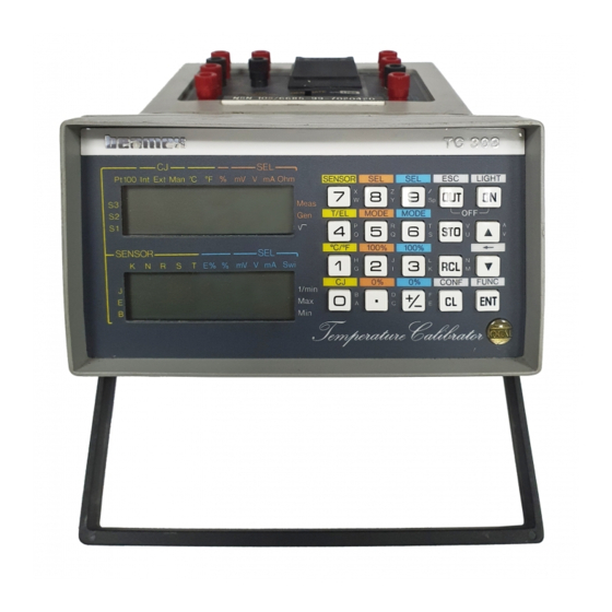
Service manual for
TEMPERATURE CALIBRATOR
TC305/TC303
Dear user,
We have made every effort to ensure the accuracy of the
contents of this manual. Should any errors be detected, we
would greatly appreciate to receive suggestions to improve the
quality of the contents of this manual.
The above not withstanding, we can assume no responsibility
for any errors in this manual or their eventual consequences.
We reserve rights to make modifications to this manual without
any further notice.
For more detailed technical data about the Service manual for
TC305/TC303, please contact the manufacturer.
© Copyright 1997
OY BEAMEX AB
P.O. Box 5
68601 Pietarsaari
FINLAND
Tel
Fax
E-mail:
Internet: http://www.beamex.com
+358 - 6 - 7840111
+358 - 6 - 7840404
sales@beamex.com
8830100 / SETC305 / 912417
Advertisement
Table of Contents
Troubleshooting


Need help?
Do you have a question about the TC305 and is the answer not in the manual?
Questions and answers