Table of Contents
Advertisement
DOCUMENTING PROCESS CALIBRATOR
Dear user,
We have made every effort to ensure the accuracy of the contents of this
manual. Should any errors be detected, we would greatly appreciate to
receive suggestions to improve the quality of the contents of this manual.
The above not withstanding, we can assume no responsibility for any errors
in this manual or their eventual consequences.
We reserve rights to make modifications to this manual without any further
notice.
For more detailed technical data about the MC4 Documenting Process
Calibrator, please contact the manufacturer.
© 2008-2016
BEAMEX OY AB
Ristisuonraitti 10
FIN-68600 Pietarsaari
FINLAND
Tel
+358 - 10 - 5505000
Fax
+358 - 10 - 5505404
E-mail:
sales@beamex.com
Internet:
http://www.beamex.com
User Guide
8811000 / MC4uEng / Version 3e
Advertisement
Table of Contents

Related Manuals for BEAMEX MC4


Summary of Contents for BEAMEX MC4
- Page 1 We reserve rights to make modifications to this manual without any further notice. For more detailed technical data about the MC4 Documenting Process Calibrator, please contact the manufacturer. © 2008-2016 BEAMEX OY AB...
- Page 2 Other trademarks are property of their respective owners. MC4 contains licensed software which requires that the source code is available for You. Please contact Beamex to obtain it. MC4 is based in part on the work of the FLTK project (http://www.fltk.org).
-
Page 3: Table Of Contents
Unpacking and Inspection ................ 4 MC4 Hardware ..................5 Connections ..................... 6 Pressure Modules ................7 Connectors on the Left Side of MC4 ..........8 Terminals ................... 8 Support for Table Top Use ............... 9 Memory ....................9 Display ...................... 9 Keyboard .................... - Page 4 Contents MC4 Options ..................24 Hardware Modules/Options ..............24 Other Devices..................25 Safety ....................26 Symbols Used ..................26 Safety Precautions and Warnings ............27 General Warnings ................28 Warnings Concerning Electrical Measurement and Generation ..28 General Warnings Concerning Pressure Measurement ....29 Warnings Concerning High Pressure ..........
- Page 5 Contents Part B, Startup and Basic Operation Starting MC4 ..................36 Startup Procedure .................. 36 Basic Mode, Defined ................37 Measuring ..................39 Current Measurement ................41 Frequency Measurement ............... 42 Pressure Measurement ................43 Connecting and Disconnecting External Pressure Modules .... 44 Zeroing a Pressure Module ..............
- Page 6 Error in Output Units ................ 84 Percentage ..................85 Scaling ..................... 86 Deviation ..................87 Redundant ..................88 Difference ..................89 Showing Data on the Additional Info Row ..........90 Resetting and Clearing Additional Info Row / Calculations....93 MC4 User Guide...
- Page 7 Resistance and RTD Measurement, Connections ....... 118 4-wire System ................118 3-wire System ................118 Using a Compensation Loop............119 2-wire System ................119 Current Measurement Parallel to a Test Diode, Connections ....120 Parallel Functions in MC4 ..............121 MC4 User Guide...
- Page 8 Supported Input/Output Signal Combinations ........128 About Instrument Calibration ..............129 Selecting the Instrument to Be Calibrated ........129 A Calibration Procedure Using MC4 ..........130 Examples of Instrument Calibration..........133 Pressure Transmitters ..............134 Temperature Indicators and Recorders ......... 136 Temperature Sensors ..............
- Page 9 Changing the Pressure Module During Calibration ......179 Zeroing a Pressure Module During Calibration ........180 Guidance Texts ..................180 Environmental Data ................180 Error Calculation Formulas ..............181 Combining Calibration Repeats ............182 Results and Memory Usage ..............182 MC4 User Guide...
- Page 10 Contents Appendixes Appendix 1, Technical Data ............184 MC4 General Specifications ..............184 Electrical Measurements ..............185 Voltage Measurement ..............185 Current Measurement ..............185 Frequency Measurement ............... 186 Pulse Counting ................186 Switch Test ..................186 Electrical Generation, Sensor Measurement and Simulation ....187 mV Measurement (T/C-Terminals) ..........
- Page 11 There are however no definite restrictions; fill in the form when you feel like it (all items need not be answered). Then send it to Beamex using one of the possibilities listed below.
- Page 12 ___________________________________________________________ 9. Did anything in the product disappoint you? In that case, please specify. ___________________________________________________________ ___________________________________________________________ 10. Any ideas You want to propose to Beamex so that we can improve our products, operations and/or services. ___________________________________________________________ ___________________________________________________________ Please fill in these fields in order to receive your surprise gift.
-
Page 13: Part A, General
General Things discussed in Part A: • An introduction to what MC4 is and what the parts of this User Guide concentrate on. • A general description of MC4's hardware. • A general description of MC4's firmware. • The modularity and options of MC4. -
Page 14: Introduction
Introduction Introduction MC4 is a compact hand-held calibrator with an easy to use graphical user interface. MC4 is a documenting Multifunction Calibrator with calibration capability of temperature, electrical and frequency signals. If a pressure module is installed, then it also handles pressure signals. -
Page 15: About This Manual
This User Guide is divided in four parts: A, B, C and D. • Part A discusses general matters. There is also a chapter about safety. • Part B describes the basic use of MC4 such as measuring signals setting up... -
Page 16: Unpacking And Inspection
Introduction Unpacking and Inspection At the factory each new MC4 passes a careful inspection. It should be free of scrapes and scratches and in proper operation order upon receipt. The receiver should, however, inspect the unit for any damage that may have occurred during transit. If there are signs of... -
Page 17: Mc4 Hardware
• Storage temperature: °C 140 °F). Note: The stickers and the batteries may be affected when storing longer periods in extreme conditions. • Humidity: 0 80 % R.H. non condensing More comprehensive specifications are available in Appendix 1. MC4 User Guide... -
Page 18: Connections
S u p p l y G e n e r a t i o n Note. The picture above is of a MC4 with an internal pressure module. Because the pressure module is an option Your MC4 may not necessarily have it. -
Page 19: Pressure Modules
Gauge Type Internal Pressure Module or it may be the only Internal Pressure module installed in MC4. The Internal Barometric Module measures the barometric pressure through a connection found on the back side of MC4. Normally nothing need to be connected to the barometric pressure module's connector. -
Page 20: Connectors On The Left Side Of Mc4
MC4 Hardware Connectors on the Left Side of MC4 The left side of MC4 (front view) has four connectors as follows: External Pressure Modules are discussed in chapter External Pressure Modules on page 7 and in Part B of this manual. -
Page 21: Support For Table Top Use
Current, Voltage, Frequency and Pulse generation and • • RTD and Resistance simulation. Support for Table Top Use The support gives you a good viewing angle when MC4 is placed on a table top. Memory MC4 maintains data very much like personal computers. Data is saved on a solid state memory that does not need any power to maintain its state. -
Page 22: Keyboard
The Enter key both starts and finishes the editing of all types of fields. On/Off and Backlight Key The On/Off key switches MC4 on and off. Press the On/Off key for about half-a-second to switch on/off. This delayed function prevents accidental on/off switching of MC4. -
Page 23: Batteries
An average operating time is approximately 4 hours. Full batteries: The upper left corner of MC4's display shows a picture of a battery. The whiter the picture is, the more acute is the need for recharging (or changing of the alkaline batteries). -
Page 24: About The Charger And The Charging Procedure
When charging is ready, only the plug symbol is shown. If MC4 is shut off and the charger is connected, a battery status bar appears. After a while an estimate of the remaining charge time appears below the battery status bar (see leftmost picture below). -
Page 25: Removing/Replacing The Batteries
Batteries Removing/Replacing the Batteries To remove or replace the batteries, perform the following procedure: 1. Turn MC4 upside down (the display facing the table top) and lift the support. 2. Unscrew the two screws holding the cover (see the picture above). -
Page 26: Capacity Indication
1590 as the "password". This resets the capacity indication to 0 %. Then "teach" the capacity of the batteries using the instructions above again. Similarly, the "password" 1599 sets the capacity to 100 %, if needed. MC4 User Guide... -
Page 27: Pc Communication With Usb
Batteries PC Communication with USB The first time you connect MC4 to a computer (using the USB cable delivered with MC4), Windows' Found New Hardware Wizard initializes wanting to install a device driver. The driver can be found at Beamex's web site (http://www.beamex.com). -
Page 28: Mc4 Firmware
MC4 Firmware MC4 Firmware MC4's firmware is saved in FLASH memory. Therefore it is relatively easy to update the firmware whenever a new version with fresh capabilities is released. See Firmware Update on page 32 for more information on updating the firmware in your MC4. -
Page 29: Basic Mode's User Interface
The second section displays the date and the third the time. Windows 1 and 2 MC4 has two windows in Basic Mode. Both windows can independently be configured to display a measurement value. They can also be assigned to more data on the extra info row as seen in the previous picture. -
Page 30: The Function Key Bar
This happens, e.g. when selecting which items are to be shown on the Additional Info row. 3. A sub menu opens allowing you to select one of available sub menu items. MC4 User Guide... -
Page 31: Configuration Windows
The view of the date/time configuration window contains selection lists and numeric fields. The view of the alarms configuration window contains check boxes and numeric fields. Descriptions of all field types are presented in the subsequent chapters. MC4 User Guide... -
Page 32: Field Types Available For Editing Data
Capture This allows you to capture and save the measured value in the Numeric field. Numeric field used for generating/simulating signals include additional editing possibilities: Spinning and Manual Stepping. More of them in part B, page 54. MC4 User Guide... - Page 33 Slow the field. Clear • for accepting the edited text. • Accept the new text by pressing the Enter key ( ) or use the previously mentioned menu option. To discard changes, use the Function Key. Cancel MC4 User Guide...
- Page 34 To quickly jump to an option, use the Numeric keys. The first press jumps to the closest option starting with the first letter stated above the Numeric key. Repeated key presses jump to options starting with subsequent letters stated above the Numeric key. MC4 User Guide...
- Page 35 The Enter key ( ) toggles the value of the check box. The Sign key ( ) also toggles the value of the check box. The Zero key ( ) clears the check box. The One key ( ) sets the check box. MC4 User Guide...
-
Page 36: Mc4 Options
MC4 Options MC4 Options MC4 includes optional hardware modules. This makes it possible to buy a calibrator with capabilities according your requirements. Hardware Modules/Options Internal Pressure Module (NPM) Available gauge pressure modules: • NPM200mC, range: ±200 mbar ±80 iwc) • NPM2C, range:-1 …... -
Page 37: Other Devices
Other Devices There is an increasing number of devices that can be used together with MC4. The following list includes devices that are already available (valid when this manual was printed): • External Pressure Modules (EXT) • Calibration hand pumps:... -
Page 38: Safety
Safety Safety The materials of MC4's case withstand normal industrial conditions. MC4 endures shocks with the help of the built in impact protectors Symbols Used The following symbols concerning electrical safety are used in MC4. Alternating current, AC Direct current, DC... -
Page 39: Safety Precautions And Warnings
Use MC4 only if you are certain of that it can be used safely. Safe use of MC4 is no longer possible if one or more of the following cases are true: •... -
Page 40: General Warnings
Safety General Warnings Do not use MC4 in any other way than as described in this User Guide. Use the MC4's battery charger in a non-hazardous indoor location only and only with Beamex MC4 calibrators. While charging, the temperature should not exceed 35 °C (95 °F). If MC4's battery charger is broken, dispose it according to local waste regulations and order a new charger from Beamex. -
Page 41: General Warnings Concerning Pressure Measurement
Booklet that is provided with the external module. Never plug a hose with your hands or put hands in front of a gas spray coming from a leakage. A gas bubble in the blood circulation can cause death. MC4 User Guide... -
Page 42: Warnings Concerning High Pressure
If a gas bubble gets into the blood circulation, it can cause death. The leak jet is particularly penetrative, if some liquid is coming with the gas. MC4 User Guide... -
Page 43: Disposal Of Waste Electrical And Electronic Equipment
Disposal of Waste Electrical and Electronic Equipment Beamex is an environmentally conscious company developing products with a view to ensure that they are easy to recycle and do not introduce hazardous materials into the environment. In the European Union (EU) and other countries with separate collection systems, waste from electrical and electronic equipment (WEEE) is subject to regulations. -
Page 44: Service
MC4. Never open the case unless have explicit instructions from Beamex or a local representative. There are, however a few things that anyone using MC4 may do. Firmware Update The quickest way to see if a new firmware version is available is checking out Beamex's web site (http://www.beamex.com). -
Page 45: Recalibrating Mc4
Please contact Beamex for details on recalibrating MC4. Cleaning MC4 If MC4 needs cleaning, use cloth soaked with a mild solution of tall oil soap (pine soap). Wait a few minutes and then clean using a cloth moistened with pure water. Never use any strong detergents. - Page 46 Service (Empty) MC4 User Guide...
-
Page 47: Part B, Startup And Basic Operation
Startup and Basic Operation Things discussed in Part B: • What happens during the startup procedure. • Measuring signals. • Generating/simulating signals. • Presenting the utilities available in a window's Tools menu. -
Page 48: Starting Mc4
Starting MC4 Starting MC4 Startup Procedure When MC4 is started, a startup picture appears. After a self test, a welcome screen appears displaying some basic information of the calibrator at hand. 9 E L C O M E If you want to view the calibrator information for a longer period,... -
Page 49: Basic Mode, Defined
Basic Mode, Defined All non-calibration related measurements and generations are per- formed in the Basic Mode. Briefly: in Basic Mode MC4 works like a high quality multimeter. When returning from MC4’s higher level operations (calibration, viewing of calibration results, calibrator and user configurations), you always return to the Basic Mode. - Page 50 • Set alarm limits • Start special measurements (min/max value etc.) • Use the ramping function • Use the stepping function Next Measuring on page 39 Generating/Simulating on page 53 Tools Menu on page 67 Alarms on page 69 MC4 User Guide...
-
Page 51: Measuring
Notes. In this manual, MC4's measurement Functions are presented in alphabetic order. The order the Functions appear on your MC4 depends on which Functions have been used most recently. A Function or a set of Functions using the same terminals can not be selected for several windows simultaneously. - Page 52 Use the utility found in Menu the F3/ Function Key for saving and retrieving settings. This is described in Part C of this manual. Read the warnings found in part A of this manual MC4 User Guide...
-
Page 53: Current Measurement
Also check the setting if you use MC4 as the power supply. When the option is checked, MC4 adds a suitable impedance to the loop to ensure HART communication. Make sure the polarity of your connections is correct. The following pictures present the correct connections depending on whether MC4 is used for providing loop supply or not. -
Page 54: Frequency Measurement
Measuring Frequency Measurement MC4 measures frequencies between 0.0027 Hz (10 cph) to 50 kHz. Frequency Measurement Function: Trigger Level Also check the setting. There you can specify the trigger level and whether to use a test voltage during the frequency measurement. -
Page 55: Pressure Measurement
Pressure Measurement Pressure Measurement MC4 supports the use of an internal pressure module (if installed). When connecting an external pressure module to MC4, it is automatically detected and there is a possibility to immediately put the connected external pressure module to use. -
Page 56: Connecting And Disconnecting External Pressure Modules
An external pressure module may be connected and disconnected at any time. If a removed module was part of an active measurement, MC4 emits a "bleep" to inform you of the fact that the external pressure module used for pressure measurement was removed. The window where the external pressure measurement was configured reverts to "None/No Function". -
Page 57: Zeroing A Pressure Module
NOTE! Zeroing a pressure module is especially important when the operating position of MC4 is changed or the location of MC4 is changed in the vertical direction. Both of the above mentioned factors affect notably on the pressure measurement modules. -
Page 58: Pulse Counting
(depending on which window is used for pulse counting) Clear Pulses and F1/ Next Pulse Generation on page 59 Frequency Generation on page 58 Frequency Measurement on page 42 Switch State Sensing on page 48 Calibration, see Part D. MC4 User Guide... -
Page 59: Resistance Measurement
M a x 6 0 , 3 0 , 1 0 0 The two leftmost terminals are used in 2-wire systems. MC4 automatically checks the connection and displays the found wiring system (2-wire, 3-wire or 4-wire) in the upper right corner of the measuring window. -
Page 60: Switch State Sensing
Also check the setting. There you can specify whether to use only a trigger voltage level or do you also want MC4 to include a test voltage to detect switches with no external potential. All voltages below the trigger level are treated as a closed contact and all voltages above the trigger level are treated as an open contact. - Page 61 This can be used to show real switch state when switch state sensing is connected to relay coil instead of relay contacts. Next Tools Menu on page 67 Alarms on page 69 Calibration, see Part D. MC4 User Guide...
-
Page 62: Temperature Measurement (Rtd)
Sensor Also check the setting. Make sure you select the same sensor type than what is connected to MC4. Otherwise your measurement results are unreliable. For information on creating custom Platinum Resistance Temperature (PRT) type RTD sensors, see Part C, chapter Custom PRT Sensors on page 106. -
Page 63: Temperature Measurement (Thermocouple)
Sensor Check the setting. Make sure you select the same sensor type than what is connected to MC4. Otherwise your measurement results are unreliable. Also select a suitable Reference Junction compensation method from the RJ Mode list. Wrong reference junction setting results in useless measurement results. -
Page 64: Voltage Measurement
M a x 6 0 V , 3 0 V , 1 0 0 m A the adjacent picture. Warning! Do not apply hazardous voltages to MC4's terminals. Next Voltage Generation on page 65. Temperature Measurement (Thermocouple) on page 51. Tools Menu on page 67. -
Page 65: Generating/Simulating
Notes. In this manual, MC4's generation/simulation Functions are presented in alphabetic order. The order the Functions appear on your MC4 depends on which Functions have been used most recently. A Function or a set of Functions using the same terminals can not be selected for several windows simultaneously. -
Page 66: Changing The Generated/Simulated Value
Spinning utility Step then press Function Key. To step through the defined steps, use the up and down arrow keys ). To toggle between the minimum and maximum value, press the Function Key. MC4 User Guide... - Page 67 To stop Stepping and return to Basic Mode, press the F1/ Function Key. Notes. You cannot exceed the minimum/maximum limits of a Function when Spinning/Stepping. The spinned/stepped value follows the resolution properties of the generated/simulated Function. MC4 remembers the Manual Step configuration settings for each generation/simulation Function. MC4 User Guide...
-
Page 68: Current Generation
Generating/Simulating Current Generation MC4 is able to generate current both in source and sink mode. In source mode MC4 provides the supply power to the loop. In sink mode an external power supply is used and MC4 controls the current flow. - Page 69 Make sure that you don't exceed the maximum current allowed by the instrument under test. If you open the current generation loop, MC4 tries to maintain the current by increasing the output voltage. If you then close the loop again, the current is first too high, but returns quickly to the correct level.
-
Page 70: Frequency Generation
See Appendix 1, Technical Data for more specific info of Duty Cycle limitations. Next Pulse Generation on page 59. Frequency Measurement on page 42. Tools Menu on page 67. Stepping on page 73 Ramping on page 76. Calibration, see Part D. MC4 User Guide... -
Page 71: Pulse Generation
, 3 0 , 1 0 0 In the Basic Mode window: Enter the amount of pulses MC4 should generate. The pulse generation starts immediately after the amount is entered. By default the additional info row at the bottom of the window displays pulses done and pulses left (icons: respectively). -
Page 72: Resistance Simulation
Resistance Simulation In resistance simulation MC4 mimics a resistor. The instrument under test generates the current for the resistance measurement. MC4 controls the voltage across its terminals so that the resistance (voltage to current ratio) corresponds to the resistance. Resistance Simulation... -
Page 73: Rtd Sensor Simulation
RTD Sensor Simulation RTD Sensor Simulation In RTD sensor simulation MC4 mimics an RTD. The instrument under test generates the current for the RTD measurement. MC4 controls the voltage across its terminals so that the resistance (voltage to current ratio) corresponds to the simulated temperature. - Page 74 Generating/Simulating Notes. In RTD simulation MC4 monitors the resistance measurement current. If the current is too high, it cannot simulate the right High Cur resistance value. In that case it shows the message " ". Accurate operation of the simulation electronics requires that the current supplied by the instrument under test does not vary rapidly.
-
Page 75: Thermocouple Simulation
MC4. MC4 mimics a thermocouple at given temperatures. To the instrument under test MC4 appears as a thermocouple at the given temperature. T/C Sensor Simulation Function: Sensor Check the setting. - Page 76 Generating/Simulating possible. In this situation, the accuracy depends on the similarity of the selected sensor in MC4 and the used sensor. Wire-wound thermocouple temperature indicators recorders are calibrated with known loop resistance, commonly ten or twenty ohms. The required resistance of the conductors is usually marked on the device.
-
Page 77: Voltage Generation
, 1 0 0 Warning! If you short circuit the voltage output, MC4 tries to maintain the voltage by increasing the output current. If you then remove the short circuit, the voltage is first too high, but returns quickly to the correct level. -
Page 78: Manually Keyed Values
This suits instruments that have an input signal not supported by MC4, but the output can be measured by MC4. Actually, the input and output may be interchanged too as long as the one of the signals is measured and the other is entered manually. -
Page 79: Tools Menu
Voltage Generation Tools Menu MC4's Basic Mode windows have utilities that add extra features to your measurements/generation/simulations. They are available in a Tools Tools window's menu. The contents of the menu varies depending on which Function is selected. This is because measurement Functions require different tools than generation/sim- ulation Functions. -
Page 80: Function Info
Function Key to move from page to page. Setup To see Function Info, enter the following menu commands: F1/ Setup or F2/ (depending on which window you want to view Tools Function Info Function Info for), F2/ from the opened menu. MC4 User Guide... -
Page 81: Alarms
When an alarm limit is exceeded, MC4 emits an audible alarm and the alarm symbol is shown with inverted colors. To acknowledge the... -
Page 82: Damping
To stop using and clear all alarm limits, select another Function or reselect the same Function. Damping Damping is useful when a measurement signal contains unwanted noise. MC4 includes a set of damping tools. To set the damping value, enter the following menu commands: Setup Setup... -
Page 83: Leak/Stability Test
Start stopped. Select F1/ and see how the test advances. The rightmost picture above is an example of an MC4 display during a test. The absolute decrease is shown beside the triangle and the average decrease per minute below. MC4 User Guide... - Page 84 MC4's accuracy is not suitable for the given task. If applicable, disable MC4's auto-off functionality during the test. If the test lasts longer than the auto-off delay, MC4 is shut down while the test is still incomplete. An external pressure module (EXT) connected to MC4 during a leak/stability test cannot be taken into use in the window were the leak/stability test is under progress.
-
Page 85: Stepping
(depending on which window you want Start Step to configure the stepping to), F1/ . This possibility is available until a new Function is selected for the window where stepping was used or MC4 is shut down. MC4 User Guide... - Page 86 Each number is a step level. The last item in the list allows you to make your own custom step definition. Custom steps are presented in chapter Custom Test Point Sets on page 101. Continues on next page MC4 User Guide...
- Page 87 103. Warning! Do not configure the range settings so that they exceed the al- lowed input range connected instrument. determines the limits of the range settings based on the selected quantity and port, not the connected instrument. MC4 User Guide...
-
Page 88: Ramping
(depending on which window you want Start Ramp to configure the ramping to), F1/ . This possibility is available until a new Function is selected for the window where ramping was used or MC4 is shut down. MC4 User Guide... - Page 89 Note. MC4 actually makes the ramp in small steps. The steps are as small as possible, slower ramps use smaller steps. MC4 User Guide...
-
Page 90: Manual Stepping
M A N U A L S T E P ( ΠΠ6 . 0 0 0 0 Start Start manual stepping by selecting the F3/ Function Key in the Close configuration window. To stop it, press F1/ Function Key (in Basic Mode). MC4 User Guide... - Page 91 "By: 'Step Size'". If applicable, set the fixed step size here. Number of Steps Active only if Step Definition field is set to "By: 'Number of Steps'". If applicable, set the number of steps here. Continues on next page MC4 User Guide...
- Page 92 Do not configure the range settings so that they exceed the al- lowed input range connected instrument. determines the limits of the range settings based on the selected quantity and port, not the connected instrument. See also: Spinning and Manual Stepping on page 54. MC4 User Guide...
-
Page 93: Display Mode And Special Measurements
In some cases these extra digits may cause rounding that differs from values that are shown on display. Notable differences between shown and manually calculated values usually mean that MC4's accuracy is not suitable for the given task. MC4 User Guide... -
Page 94: Error
Beware of the problems that may result in not seeing the true measurement value. For help on making Custom Transfer Functions, see Part C, chapter Custom Transfer Functions on page 103. MC4 User Guide... -
Page 95: Error In Input Units
Error displayed in input units is in all other ways similar to error displayed in error percentage. The only difference is in how the calculated error is displayed. For configuration details, refer to Error % on page 82. MC4 User Guide... -
Page 96: Error In Output Units
Error displayed in input units is in all other ways similar to error displayed in error percentage. The only difference is in how the calculated error is displayed. For configuration details, refer to Error % on page 82. MC4 User Guide... -
Page 97: Percentage
Percentage display is active, the second item replaces the windows' main measurement data. Beware of the problems that may result in not seeing the true measurement value. For help on making Custom Transfer Functions, see Part C, chapter Custom Transfer Functions on page 103. MC4 User Guide... -
Page 98: Scaling
Scaling display is active, the second item replaces the windows' main measurement data. Beware of the problems that may result in not seeing the true measurement value. For help on making Custom Transfer Functions, see Part C, chapter Custom Transfer Functions on page 103. MC4 User Guide... -
Page 99: Deviation
Warning. Keep in mind that when the displayed deviation reading is small compared to the actual reading, a significant part of the deviation value measurement error. specifications measurement errors actual measurement level. MC4 User Guide... -
Page 100: Redundant
If the readings differ more than the entered limit value, MC4 gives an audible alarm. The selected main measurement is shown normally. The secondary... -
Page 101: Difference
Difference value measurement error. specifications measurement errors actual measurement level. If the measuring spans of the selected ports are different, make sure you do not exceed the measurement range of either port. MC4 User Guide... -
Page 102: Showing Data On The Additional Info Row
Displays the found minimum value after a measurement was started or it was reset. Rate of Change Value (unit 1/min) Displays the calculated rate of change value (units/min) found after a measurement was started or the calculation was reset. MC4 User Guide... - Page 103 All Error Display Modes as well as Percentage, Scaling and Deviation measurement. Deviation Reference Available when deviation measurement is active. This is the entered reference value MC4 uses to calculate the measurement's deviation from. Redundant Measurement (Secondary Measurement) The secondary measurement used during redundant measurement.
- Page 104 Displays the temperature of the reference junction in use. Available °F or for T/C Sensor Measurement and T/C Sensor Simulation Functions. Sensor Resistance Displays the real resistance MC4 is measuring or simulating for an Ω RTD sensor Function. MC4 User Guide...
-
Page 105: Resetting And Clearing Additional Info Row / Calculations
Activating a Display Mode or a Special Measurement often replaces them with data related to the activated Display Mode or Special Measurement. Any previously activated minimum, maximum or rate of change calculations are still working, but are no longer shown (until selected to be shown again). MC4 User Guide... - Page 106 Tools Menu (Empty) MC4 User Guide...
-
Page 107: Part C, Advanced Operation And Configurations
Advanced Operation and Configurations Things discussed in Part C: • Advanced tools found in the Utilities Menu. • Help on how to create customized test point sets and transfer functions. • Related information: Useful during pressure measurement, thermocouple measurement/simulation and resistance/RTD measurement/simulation. -
Page 108: Utilities Menu
Basic Mode by pressing F3/ Menu About This Calibrator Opens a window presenting basic information of MC4. ) B O U T T H I S C A L I B R A T O R M o d e l... -
Page 109: Instrument Calibration
About the second item on the list shown in the leftmost picture above: Restore Pre-OFF Settings MC4's startup is made as straight forward as possible. It does not automatically restore its more advanced functions (display mode, special measurements etc.) used when MC4 was shut off. By... -
Page 110: Date/Time
The time must always be given in the 24 hour format no matter what the configured time format is. Date and time will be immediately updated when you change the value of any of the time related fields. MC4 User Guide... -
Page 111: General Settings
Error Volume Options: Net Frequency 50 Hz and 60 Hz. Note that wrong net frequency setting affects the accuracy of MC4. A text field for entering owner's name etc. Owner This data is shown in the Welcome Screen. MC4 User Guide... -
Page 112: Calibrator Adjustment
Immediately shuts down the calibrator. Calibrator Adjustment Opens a window to start the recalibration and adjustment of MC4. See Appendix 2 for instructions on how to recalibrate MC4. 1 6 . 0 8 . 2 0 0 7... -
Page 113: Custom Test Point Sets
Calibrator Adjustment Custom Test Point Sets MC4 has a comprehensive set of pre-entered test point sets (steps). If however they are not suited for your needs, you can create your own test points as presented here. In Basic Mode, custom test point definition can be started from the... - Page 114 Hints! The point values need not be in ascending order or even inside the range limits. To force MC4 to stay in one point for a longer time, enter the same point value to several successive points. Notes. The step values are saved as floating point number percentage values so the steps may be used for any Function and range.
-
Page 115: Custom Transfer Functions
Calibrator Adjustment Custom Transfer Functions MC4 has a pre-entered set of standard transfer functions. If however they do not suit your needs, you can create your own transfer functions as presented here. In Basic Mode, custom transfer function definition can be started... - Page 116 "User:" and the row ends with a chevron pointing right " ". This indicates that the point set may be edited. Hint! The maximum Input/Output pair values may be outside the ranges' maximum values. MC4 User Guide...
- Page 117 The available free memory defines how many custom transfer functions and Input/Output pairs may be saved. If there is not enough memory left to save a custom transfer function, MC4 displays an error message suggesting that you first free some memory and then retry adding a custom transfer function.
-
Page 118: Custom Prt Sensors
Custom PRT Sensors Custom PRT Sensors Although MC4 has a wealth of pre entered standard Platinum Resistance Temperature (PRT) type RTD sensors, some additional sensors definitions may be needed. This especially when a PRT sensor is used as a reference sensor. These sensors often have custom coefficients in their Callendar - van Dusen equation. -
Page 119: Callendar - Van Dusen Equation
For standard sensors the factors A, B and C are already defined, but real life (reference) sensors may require slightly different factors. Note. Callendar - van Dusen equation applies to Platinum Resistance Temperature (PRT) type RTD sensors only. Other types of RTD sensors cannot be customized using this equation. MC4 User Guide... -
Page 120: Custom Pressure Units
Custom Pressure Units Custom Pressure Units MC4 has a comprehensive set of pre-entered pressure units. If however they are not suited for your needs, you can create up to four custom pressure units. To define custom pressure units, configure one of the Basic State's... -
Page 121: Related Information
A typical example of this is temperature measurement using a thermocouple. It is not enough to select the correct Function in MC4. The Sensor type and the Reference Junction Mode has to be set accordingly, too. Wrong settings give erroneous results. -
Page 122: Things To Consider When Measuring Pressure
Related Information Things to Consider when Measuring Pressure General MC4 can measure pressure with its internal pressure module or with external pressure modules. If a barometric module is present, the measurement results of other modules can be shown either as absolute pressure or as gauge pressure. -
Page 123: Pressure Modules And Their Naming Conventions
-200 to +200 mbar (-3 to +3 psi) pressure range. The names of MC4's internal pressure modules start with the letters NPM. The names also include numbers and possible additional letters as follows: •... -
Page 124: Square Rooting
Pressure transmitters or converters used for flow measurement often have square rooting character. Here are a couple of examples on how you can configure MC4 to take into account the instrument's square rooting character: 1. Set the Display Mode of window that measures the... -
Page 125: Thermocouple Measurement/Simulation, Connections And Troubleshooting
MC4's "T/C" terminals. To select this compensation method, set the window's Function to field " Sensor " or " ", make sure the Measurement... -
Page 126: External Reference Junction
None (0 °C): To be used when: • The Reference Junction temperature is fixed to 0°C (using, e.g. ice) and MC4 is not used for measuring the Reference Junction temperature. • The Reference Junction temperature is controlled with 0°C set point. - Page 127 • The Reference Junction temperature is controlled and the controller's set point is not 0°C. Note: this method is of use only if the accuracy of the controller is better than MC4's own Reference Junction. • A compensation box is used and the Reference Junction temperature setting is other than 0°C.
- Page 128 T / C s i g n a l r e c e i v e r M a x 6 0 , 3 0 , 1 0 0 See also Internal Reference Junction on page 113 MC4 User Guide...
-
Page 129: Error Situations
The instrument to be calibrated uses • during thermocouple simulation. voltage pulses to detect an open sensor. When MC4 detects these pulses, it tries to compensate for them, which causes the unstable output. Prevent these pulses for the time of calibration. Refer to... -
Page 130: Resistance And Rtd Measurement, Connections
If possible, use 4-wire connection to eliminate the effect of wiring resistance. The special resistance measurement sequence of MC4 eliminates the thermovoltages of the resistance measurement circuit. MC4 continuously checks the connection type during resistance and RTD measurement. -
Page 131: Using A Compensation Loop
M a x 6 0 , 3 0 , 1 0 0 If the compensation loop and the connection wires of the resistor are identical, MC4 can compensate for the resistance of the connection wires. 2-wire System When 2-wire system is used, MC4 displays the symbol shown on the left. -
Page 132: Current Measurement Parallel To A Test Diode, Connections
Related Information Current Measurement Parallel to a Test Diode, Connections The impedance of MC4's milliampere input is low enough to enable current measurement parallel to a test diode in a 20 mA circuit. Plus Side Test T e m p e r a t u r e / G e n e r a t e... -
Page 133: Parallel Functions In Mc4
One electrical measurement and one electrical generation/simu- lation in the terminals. Temperature / Generate Additionally, all of the connectors on the left side of MC4 may have an independent task. Notes. The Barometric module can always be used for pressure type conversion, even if it is already active in any window. - Page 134 Related Information (Empty) MC4 User Guide...
-
Page 135: Part D, Calibration
• General presentation of what cal- ibration is and the phases of a typical calibration procedure. • A description of a calibration procedure using MC4. • Some application examples on how to perform the calibration of certain instruments. • Creating, editing and deleting In- struments. -
Page 136: General
MC4 supports stand-alone calibration and off-line calibration. The following list briefly describes these methods: • In stand-alone calibration, all instrument and calibration result data is stored in MC4's memory. No external calibration data- base is used. • In off-line calibration (sometimes also called batch calibra- tion), the instrument data is downloaded from a calibration software. -
Page 137: Phases Of Instrument Calibration
N o . o f y e s r e p e a t s d o n e ? E n d The picture gives a general view of the phases in a typical calibration procedure. MC4 User Guide... -
Page 138: As Found Calibration
181. Adjustment If the found error is outside acceptable limits (reject limits), the in- strument needs adjustment. Activate one of MC4's error display modes to help you minimize the error (see chapter Tools Menu in part B). Use the instrument's ZERO adjustment at lower end of the range. -
Page 139: As Left Calibration
"lowering the graph". As a result, the error min- imum is at approx. 30 % and 70 % of the span. Note that these adjustment strategies are just examples. There is an unlimited amount of "correct" ways to adjust an instrument. MC4 User Guide... -
Page 140: Supported Input/Output Signal Combinations
Consider the type of your instrument before doing a calibration: • Which Function (and possible additional settings) is needed in MC4 to determine the instrument's input? Select a corre- sponding column from the table below. • Which Function (and possible additional settings) is needed in MC4 to determine the instrument's output? Select a corre- sponding row from the table below. -
Page 141: About Instrument Calibration
About Instrument Calibration Note. See Part C, Advanced Operation and Configurations, chapter Parallel Functions in MC4 for additional info on what kind of simul- taneous tasks MC4 is able to do. About Instrument Calibration This chapter and its subchapters present a basic approach on how to perform a calibration with existing instrument data. -
Page 142: A Calibration Procedure Using Mc4
How the instrument is identified in the Instrument List depend on en- tered instrument data. For more information, see page 157. A Calibration Procedure Using MC4 When you have selected an instrument for calibration, a window like the leftmost picture below opens. - Page 143 • If an external device (e.g. a pressure controller) generates the input signal, set the target value for the input signal as the external device's set point. MC4 measures the output of the external device, i.e. instrument's input signal. • If the input signal is generated manually (e.g. a pressure pump) set the input signal into required level.
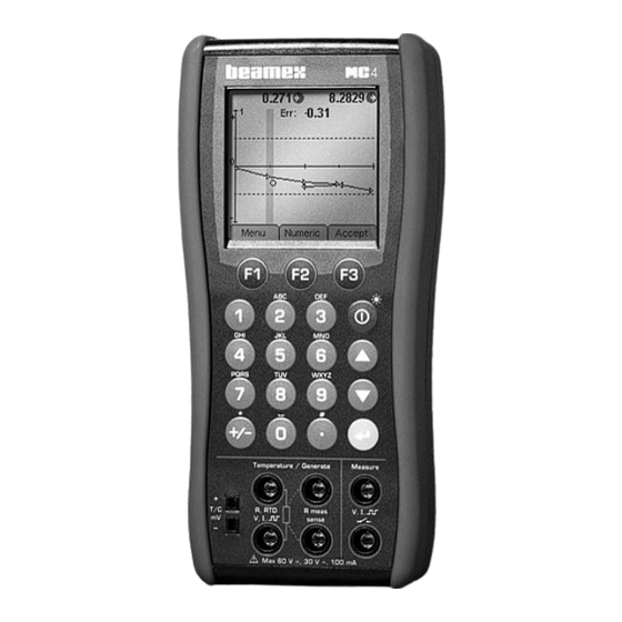
- Page 144 Calibration Window Menu on page 145. 3. When the calibration run is 0 . 0 0 4 . 0 8 0 2 ready, MC4 opens a win- E r r : 0 . 5 0 dow telling whether the cal-...
-
Page 145: Examples Of Instrument Calibration
The following pages contain a few examples of how to calibrate an instrument using MC4. When uncertain, consult Part B of this manual for information on how to connect instruments and configure the windows of MC4 to suit the instrument's needs. The following calibration examples are presented in this manual: Pressure Transmitters on page 134, •... -
Page 146: Pressure Transmitters
Both the input and output signal range should be measurable with MC4. Note. In order to perform a pressure transmitter calibration, the MC4 at hand needs to have either a suitable internal pressure module or an external pressure module has to be connected to MC4. - Page 147 4. Proceed to next calibration point (step 2) if applicable. When the calibration run is ready, save or reject the results as de- scribed in chapter A Calibration Procedure Using MC4 on page 130. 5. Either do another calibration run, adjust the instrument or end...
-
Page 148: Temperature Indicators And Recorders
MC4. The instrument's output (reading) is manually entered into MC4. Preparations 1. Connect suitable terminals in MC4 to the input connectors of the indicator/recorder. 2. If the sensor to be simulated is a thermocouple, select one of the following reference junction methods: •... - Page 149 When calibrating a temperature instrument with a detachable sensor (the input signal is simulated with MC4), use this example as the source for the input signal part. You may set the display resolution for the entered indication/reading...
-
Page 150: Temperature Sensors
Examples of Instrument Calibration Temperature Sensors This procedure suits temperature sensors no matter if they are RTDs or thermocouples. The sensor's output signal is measured with MC4. The reference temperature is either measured with MC4 or manually entered into MC4. i... - Page 151 5. Proceed to next calibration point (step 2) if applicable. When the calibration run is ready, save or reject the results as de- scribed in chapter A Calibration Procedure Using MC4 on page 130. 6. Either do another calibration run, adjust the instrument or end...
-
Page 152: Pneumatic Pressure Transmitters And Converters
To be able to perform the calibration, an internal pressure module need to be installed and an external pressure module need also be connected to MC4. The example picture below has the instrument's input connected to the internal pressure module and the instrument's output connected to the external pressure module. - Page 153 F1/ Menu Instrument Output Absolute . Then you may select " " as the pressure type and MC4 uses the manually entered barometric pressure to display the measured gauge pressure as absolute pres- sure. MC4 User Guide...
-
Page 154: Electrical Limit Switches
Calibration Start 1. In the calibration window: press F3/ 2. MC4 does a Prescan if it is enabled. During the prescan, MC4 searches for approximate values for actuating and deac- tuating point. This speeds up the final test without sacrificing accuracy. - Page 155 About Instrument Calibration 3. The actual test is done automatically: MC4 slowly increases the input signal until the switch actuates and continues by de- creasing the input signal until the switch deactuates. MC5’s screen displays the obtained data as the test advances.
- Page 156 These instructions can be adapted for any kind of switch. Change the input signal connections/settings according to the instrument's input signal. When calibrating an electrical instrument and the input signal is gen- erated with MC4, use this example as the source for the input signal part. MC4 User Guide...
-
Page 157: Calibration Window Menu
Note that Function Key allows you to jump between instrument input range's minimum and maximum. This feature is useful when the instrument's input signal is generated/simulated with MC4. Continues on next page MC4 User Guide... - Page 158 Tools menu is described in chapter Tools Submenu on page 149. Result History Visible only when saved calibration data exists for the selected instrument in MC4's memory. More of viewing results in chapter Viewing Calibration Results on page 174.
-
Page 159: Menu When A Calibration Is Running
Available only when there are previ- ously accepted calibration points. Skip Point Allows you to skip current calibration point. Advances to the next point (if applicable) without saving the results of current point. Continues on next page MC4 User Guide... - Page 160 Tools menu is described in chapter Tools Submenu on page 149. Result History Visible only when saved calibration data exists for the selected instrument in MC4's memory. More of viewing results in chapter Viewing Calibration Results on page 174.
-
Page 161: Tools Submenu
Special Measurements on page 81. Note. The following Tools submenu items have additional conditions as to Damping Leak / Stability Test Dis- when they are visible: play Mode / Specials are available only before a calibration is started. MC4 User Guide... -
Page 162: Maintaining Mc4'S Instrument Database
Maintaining MC4's Instrument Database Maintaining MC4's Instrument Database MC4 allows you to create a plant structure with instruments without any limitations except the available memory. The plant structure and its instruments are together saved MC4's instrument database. When you move from Basic Mode to Instrument Calibration Mode... - Page 163 (e.g. CMX Calibration Maintenance Management Software). Optionally they can be created manually by using the tools available in the instrument list window's menu. The menu opens from Function . More of the Instrument List Window's Menu in the next chap- ter. MC4 User Guide...
-
Page 164: Instrument List Window Menu
If an instrument is highlighted, some basic instrument data is shown. Among the data there is the selected MC4 Function for the instrument's input and output. More By pressing F2/... - Page 165 Allows you to rename the highlighted plant structure level. Delete All Instruments . Deletes • all instruments and their possible results found in MC4's memory. Delete All Results . Deletes the • calibration results of all instruments found in MC4's memory.
- Page 166 Maintaining MC4's Instrument Database MENU ITEM DESCRIPTION (cont.) Create New A submenu opens with the following op- tions: Create New Instrument , which • opens the instrument data windows for adding a new instrument. More of all instrument data windows and...
- Page 167 Instrument List Window Menu Notes. When creating a new instrument, MC4 takes the Input and Output Functions based on Functions active in Basic Mode's two windows. When an instrument to be added is similar to an instrument already existing in MC4's memory, here's a method for adding it quickly: 1.
-
Page 168: Editing Instrument Data
Enter Key ( ). Notes. If you edit an instrument in MC4 and it was originally sent from a cal- ibration software, the software notices the difference(s) when you upload the results. Then, depending on your user rights in the soft- ware, you are either allowed to save the results together with updat- ed instrument data or you are refused to save anything. -
Page 169: Position Data Page
101. Level 10.2" What identifies the instrument in MC4's instrument list. MC4's instrument list displays one of the following fields/text in the instrument list. The list is hierarchical, i.e. the uppermost is shown if it is not empty. The last text is shown if all of the previously men- tioned fields are empty: 1. -
Page 170: Device Data Page
Maintaining MC4's Instrument Database Device Data Page Device related data. FIELD DESCRIPTION Device ID Device ID is the field, that identifies an in- strument. Serial Number A field for entering the instrument's serial number Manufacturer A field for entering the instrument's manu-... -
Page 171: Input Data Page
(first field in the list be- low): FIELD DESCRIPTION Function The function needed in MC4 to determine the instrument's input. Display Resolution Select a suitable display resolution from the available list. This field is visible when the selected... - Page 172 Maintaining MC4's Instrument Database FIELD DESCRIPTION (cont.) Switch Sound Defines when MC4 emits a sound when the switch changes its state. Options: No Sound Sound Open Sound Closed When Changed This field is visible when the selected Function is: Switch...
-
Page 173: Output Data Page
(first field in the list below): FIELD DESCRIPTION Function The Function needed in MC4 to determine the instrument's output. Display Resolution Select a suitable display resolution from the available list. This field is visible when the selected... - Page 174 Maintaining MC4's Instrument Database FIELD DESCRIPTION (cont.) Switch Sound Defines when MC4 emits a sound when the switch changes its state. Options: No Sound Sound Open Sound Closed When Changed This field is visible when the selected Function is: Switch...
-
Page 175: Function Data Page
This field is visible when the selected Function is: Switch Nominal Set & Re- Enter the switch's nominal set and reset (actuating and deactuating) point values here. This field is visible when the selected Function is: Switch Continues on next page MC4 User Guide... - Page 176 This field, just as the previ- ous one are usable, when the instrument at hand has several similar functions. Warning! If you have received multi-channel in- struments from a calibration software, do not edit the channel number in MC4. MC4 User Guide...
-
Page 177: Procedure Data Page
Editing Instrument Data Procedure Data Page MC4 Data related to the calibration procedure. Since the fields for switches and non-switches (i.e. regular instru- ments) vary significantly, they are presented in separate tables. Procedure fields for non-switches (Procedure fields for switches are presented further on ) - Page 178 Maintaining MC4's Instrument Database FIELD DESCRIPTION (cont.) Automatic Check if you want MC4 to automatically accept calibration points. See also addi- Calibration Point tional settings further on in this table and Acceptance chapter Accepting Calibration Points Automatically on page 178.
- Page 179 Procedure fields for switches FIELD DESCRIPTION Automatic Check if you want MC4 to automatically accept calibration points. See also chapter Calibration Point Accepting Calibration Points Automati- Acceptance cally on page 178. Switch Ramp/Scan Switch's set point should be within this range.
- Page 180 This speeds up the final test without sacrificing accuracy. The prescan test is done only once in a calibration. Note that prescan is of use only when MC4 is generating/simulating the switch's out- put. Update Switch Active only if previous check box is set.
- Page 181 Keep in mind, however, that a de- fective switch is always inconsistent, no matter how you increase the delay. Switch Test Cycles How many test cycles (set/reset) is done for each As Found or As Left calibration run. MC4 User Guide...
-
Page 182: Error Limits Data Page
Calibration fails if found error exceeds this value at some point. Adjust if > If value is other than zero, MC4 suggests that you do adjust the instrument if found error exceeds this value at some point. Do not adjust if <... - Page 183 To do this, set this check box. This field is visible for switches only Reject if > Active only if previous Check box is set. Enter a reject error limit for the reset point. MC4 User Guide...
-
Page 184: General Data Page
Maintaining MC4's Instrument Database General Data Page This is additional data typically received from a calibration software. You also may enter/edit the data in MC4. FIELD DESCRIPTION Work Order The work order number/code for the cali- bration of the current instrument. -
Page 185: Saving An Edited Instrument
When you choose , the original instrument (source) is left unchanged and a new instrument is created based on the edited instrument data. Possible calibration result data is not copied, but stays linked to the original instrument. MC4 User Guide... -
Page 186: Viewing Calibration Results
(and see more results if there are more results that can be seen on the display). Press Enter key ( ) to see more data of high- lighted row. See also chapter Extra Information Saved With Cali- bration Point Data on page 177. MC4 User Guide... -
Page 187: How To Choose Which Calibration Run Is Viewed
D e l e t e A l l R e s u l t s (correspondingly newer) results available and the results have M e n u M o r e C l o s e the same instrument data. Result History To see a list of all results, select MC4 User Guide... -
Page 188: Deleting Calibration Results
There you may also delete all results for the currently selected instrument leaving the results of other instru- ments intact. More of the instrument list window menu in chapter In- strument List Window Menu on page 152. MC4 User Guide... -
Page 189: Additional Calibration Related Information
D chapters. Extra Information Saved With Calibration Point Data Along with the input and output values, MC4 saves the following da- ta for each calibration point (when applicable). Some data is stored automatically and some may be manually entered. -
Page 190: Accepting Calibration Points Automatically
1. As long as the input and/or output is unstable (symbol visible in Numeric Mode), calibration points are not automatically accepted. 2. When both input and output are stable, MC4 waits for a Setpoint Delay time period defined in field. -
Page 191: Changing The Pressure Module During Calibration
1. Select this menu option, 2. Remove the currently connected Ex- ternal Pressure Module. 3. Wait until MC4 emits a "bleep" in- forming that the removal of the Ex- ternal Pressure Module is noticed. 4. Connect another External Pressure Module. -
Page 192: Zeroing A Pressure Module During Calibration
172. If you use a calibration software to add calibration point level notes, they may be also sent to MC4. These are also shown at appropriate stages during a calibration run. However, point level notes cannot be edited in MC4. -
Page 193: Error Calculation Formulas
(using the trans- ideal fer function equation) to input, i.e. the input value that theoretically produces the measured output value. is the measured input for a calibration point. MC4 User Guide... -
Page 194: Combining Calibration Repeats
Results and Memory Usage If you are calibrating instruments using off-line method then please keep in mind this: When you upload the results from MC4 to the cal- ibration software, the results are by default also left in MC4's memory. Delete results to free memory in MC4 as described in chapter Instrument List Window Menu on page 152. -
Page 195: Appendixes
Appendixes Appendix 1 Technical Data ......184 Appendix 3 Index ........203... -
Page 196: Appendix 1, Technical Data
Appendix 1, Technical Data Appendix 1, Technical Data MC4 General Specifications Feature Specification Display 60 mm x 60 mm (2.36" x 2.36"), 160 x 160 pixels, back lit LCD Weight 820 g (1.8 lbs) Dimensions 215 mm (8.5") x 102 mm (4") x 49 mm (1.9") -
Page 197: Electrical Measurements
> 25 mA, short circuit protected Output voltage 24 V ± 10% Output impedance 300 ohm ± 20% in HART compatible mode Uncertainty includes reference standard uncertainty, hysteresis, nonlinearity, repeatability and typical long term stability for mentioned period. (k=2) MC4 User Guide... -
Page 198: Frequency Measurement
24 V 35 mA (2 V) Voltage level detection Input impedance > 1 Mohm Trigger level -1 14 V in 1 V steps Uncertainty includes reference standard uncertainty, hysteresis, nonlinearity, repeatability and typical long term stability for mentioned period. (k=2) MC4 User Guide... -
Page 199: Electrical Generation, Sensor Measurement And Simulation
Add 0.0008 % RDG /°F to spec. outside 64.4 82.4°F Max. load current 5 mA Load effect < 5µV/mA Supported units V, mV, µV Uncertainty includes reference standard uncertainty, hysteresis, nonlinearity, repeatability and typical long term stability for mentioned period. (k=2) MC4 User Guide... -
Page 200: Voltage Generation
750 ohm @20 mA, 600 ohm @25 mA impedance (source) Max loop voltage 60 V (sink) Supported units mA, µA Uncertainty includes reference standard uncertainty, hysteresis, nonlinearity, repeatability and typical long term stability for mentioned period. (k=2) MC4 User Guide... -
Page 201: Resistance Measurement
(pulsed currents) Supported units ohm, kohm Uncertainty includes reference standard uncertainty, hysteresis, nonlinearity, repeatability and typical long term stability for mentioned period. (k=2) Specification valid with an excitation current >0.2 mA (0...400 ohm), >0.1 mA (400...4000 ohm) MC4 User Guide... -
Page 202: Frequency Generation
0.0005 ... 10000 Hz Duty Cycle 1 ... 99 % (0.0009 500 Hz), high/low time: minimum 25µs, maximum 1165 s Uncertainty includes reference standard uncertainty, hysteresis, nonlinearity, repeatability and typical long term stability for mentioned period. (k=2) MC4 User Guide... -
Page 203: Temperature Measurement And Simulation
4-wire measurement: 0.06 °C Simulation 0.12 °C Uncertainty includes reference standard uncertainty, hysteresis, nonlinearity, repeatability and typical long term stability for mentioned period. (k=2) Specification valid with an excitation current >0.2 mA (0...400 ohm), >0.1 mA (400...4000 ohm) MC4 User Guide... - Page 204 • Pt500 (385) • Pt100 (3923) Uncertainty includes reference standard uncertainty, hysteresis, nonlinearity, repeatability and typical long term stability for mentioned period. (k=2) Specification valid with an excitation current >0.2 mA (0...400 ohm), >0.1 mA (400...4000 ohm) MC4 User Guide...
- Page 205 • NiFe3000 (262) • Cu 53M (426) • Pt500 (391) • Cu 100M (426) • Pt1000 (375) • Pt100 (389) • Pt10 (3923) • Pt50 (3924) • Pt100 (3924) • Pt200 (3924) • Pt500 (3924) • Pt1000 (3924) MC4 User Guide...
-
Page 206: Thermocouple Measurement And Simulation
Uncertainty includes reference standard uncertainty, hysteresis, nonlinearity, repeatability and typical long term stability for mentioned period. (k=2). Uncertainty does not include reference junction uncertainty. IEC 584, NIST MN 175, BS 4937, ANSI MC96.1 ±0.02 % of thermovoltage + 4 µV MC4 User Guide... - Page 207 Uncertainty includes reference standard uncertainty, hysteresis, nonlinearity, repeatability and typical long term stability for mentioned period. (k=2). Uncertainty does not include reference junction uncertainty. IEC 584, NIST MN 175, BS 4937, ANSI MC96.1 ±0.02 % of thermovoltage + 4 µV MC4 User Guide...
- Page 208 (k=2). Uncertainty does not include reference junction uncertainty. IEC 584, NIST MN 175, BS 4937, ANSI MC96.1 ±0.02 % of thermovoltage + 4 µV DIN 43710 ASTM E 988 - 96 MC4 User Guide...
- Page 209 Uncertainty includes reference standard uncertainty, hysteresis, nonlinearity, repeatability and typical long term stability for mentioned period. (k=2). Uncertainty does not include reference junction uncertainty. ±0.02 % of thermovoltage + 4 µV ASTM E 988 - 96 ASTM E 1751 - 95e1 MC4 User Guide...
-
Page 210: Pressure Modules
With barometric option add 0.1 kPa (0.0146 psi) uncertainty for absolute pressure measurement. Uncertainty includes reference standard uncertainty, hysteresis, non-linearity, repeatability and typical long term stability for mentioned period (k=2). Every internal/external pressure module’s range may be displayed also in absolute pressure if the Barometric Module (B) is installed. MC4 User Guide... - Page 211 M5 (10/32") female NPM160: G 1/8” female (parallel ) All others: G1/8” (ISO228/1) female. A conical 1/8” BSP male with 60° internal cone adapter included for Beamex hose set. Wetted parts AISI316 stainless steel, Nitrile rubber. Pressure media Barometric option:...
-
Page 212: External Pressure Modules (Ext), High Accuracy
Accuracy includes hysteresis, nonlinearity, repeatability and reference standard uncertainty (k=2). 1 Year Uncertainty includes hysteresis, nonlinearity, repeatability and typical long term stability for mentioned period (k=2). Every internal/external pressure module’s range may be displayed also in absolute pressure if the Barometric Module (B) is installed. MC4 User Guide... - Page 213 3.2 mm (1/8") included. Hose included. EXT100m, EXT400mC, EXT1C, EXT2C, EXT6C, EXT20C: G1/8” (ISO228/1) female. A conical 1/8” BSP male with 60° internal cone adapter included for Beamex hose set. EXT60 to EXT1000 G ¼” (ISO228/1) male Wetted parts AISI316 stainless steel, Hastelloy, Nitrile rubber.
-
Page 214: External Pressure Modules (Ext), Standard Accuracy
Every internal/external pressure module’s range may be displayed also in absolute pressure if the Barometric Module (B) is installed. All standard accuracy external pressure modules are also compatible with Beamex MC5 and MC5P Calibrators (firmware version 1.90 and onwards). All specifications are subject to change without prior notice... -
Page 215: Appendix 2, Index
Acknowledging ........... 70 Resetting ............ 70 As Found calibration ......126 As Left calibration ........127 Automatically Accepting About MC4, Window ........ 96 Calibration Points ........178 About This Manual ........3 Auto-off Delays ........99 Absolute Error ........181 Accepting Calibration Points Automatically ......... - Page 216 Values ............54 Phases ............125 Charger ............33 Plant Structure ........129, 151 Check Boxes ..........24 Pneumatic Pressure Cleaning MC4 ..........34 Transmitter ..........140 Clearing the Additional Info Position Data ..........157 Row ............93 Pressure Converter ........140 Pressure Transmitters ......134 Combining Calibration Procedure Data ........
- Page 217 Selection Lists ..........23 Environment Pressure Unit ....154 Status Bar ........... 18 Environmental Data ....... 180 Text Fields ..........22 Equation ..........107 Updating ..........17, 33 Equations, Error Calculation ....181 User Interface ..........18 MC4 User Guide...
- Page 218 Voltages ............65 Keyboard Arrow Keys ..........10 Backlight Key ..........10 Enter Key ............ 10 Function Keys ..........10 Hardware ........... 5 Numeric Keys ..........10 On/Off Key ..........10 Keying Values into MC4 ......66 Icons ............90 MC4 User Guide...
- Page 219 Owner ............99 Manually Keyed Values ......66 Maximum value ........90 Maximum Value Resetting ............ 93 Maximum-Minimum ......... 91 Parallel Functions in MC4 ...... 121 Measurement Pausing Calibration ........ 147 Test Diode Connections ......120 PC Communication, Driver ...... 15 Measuring Percent of Output Span Error ....
- Page 220 Rate of Change ........90 ulation ............ 121 Resetting ............. 93 Sinking Current ........56 Recalibrating MC4 ......... 100 Skip Calibration Point ......147 Redundant Measurement ....88, 91 Software ..........17, 33 Redundant Reference ......91 Sourcing Current ........56...
- Page 221 Testing Leakage/Stability ....71, 149 Stability Test ........71, 149 Text Fields ..........22 Stand ............9 Thermocouple Simulation ......63 Starting MC4 ........17, 36 Thermocouple Types Status Bar ..........18 Optional ............ 197 Stepping ..........73 Thermovoltage Measurement ....92 Support .............
- Page 222 Transfer Functions, Custom ....103 Troubleshooting thermocouple measurement ....117 Warnings ..........28 Typographical Conventions ......3 Zeroing a Pressure Module ....45, 180 Undo Calibration Point ......147 Unpacking and Inspection ......4 Updating the Firmware ....... 17, 33 MC4 User Guide...
- Page 223 Notes Notes MC4 User Guide...
- Page 224 Notes MC4 User Guide...
Need help?
Do you have a question about the MC4 and is the answer not in the manual?
Questions and answers