Table of Contents
Advertisement
Quick Links
Advertisement
Table of Contents

Subscribe to Our Youtube Channel
Related Manuals for Hunter 24' Titan


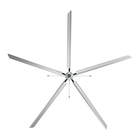
Summary of Contents for Hunter 24' Titan
- Page 1 HVLS IN STALLAT ION MANUA L...
-
Page 2: Table Of Contents
Con ten ts LEGACY The Hunter legacy is not BEFORE YOU BEGIN only about quality—it’s Safety & Precautions about longevity. We Fan Placement invented the ceiling fan. Tools Needed In The Box We build fans that last, Pre-Installation Checklist fans that are designed as INSTALLATION fans. -
Page 3: Before You Begin
SAFETY & PRECAUTIONS BEFORE YOU BEGIN Important Safety Information To prevent SERIOUS INJURY, DEATH, and PROPERTY DAMAGE, you should read, understand, and follow the warnings and instructions in this manual before installing or operating the fan. READ AND SAVE THESE INSTRUCTIONS. This manual must always be kept with the fan and should remain with the fan if it is transferred or sold. - Page 4 Do not make any changes to any part of the fan without first consulting Hunter Industrial. Installation is to be in accordance with ANSI/NFPA 70: National Electrical Code and local codes.
- Page 5 EVERY fan. The Retention Cable, if installed per Hunter Industrial specifications, can limit the distance the fan could fall in the unlikely event of mounting system failure. Failure to install and to secure the retention cable will void your warranty.
-
Page 6: Fan Placement
FAN PLACEMENT BEFORE YOU BEGIN ALWAYS MOUNT FAN SO THE BOTTOM EDGE OF BLADE TO THE FLOOR IS AT LEAST 10 FEET FROM THE FLOOR AND AT LEAST 25% OF FAN DIAMETER FROM THE CEILING. A large fan, 20 to 24 foot in diameter, performs best at 20 to 30 feet above the floor, but acceptable performance has been demonstrated as low as 10 feet and as high as 50 ft. - Page 7 FAN PLACEMENT BEFORE YOU BEGIN FAN PLACEMENT: FAN SPACING CHARTS TITAN MIN-MAX MIN-MAX MIN-MAX 24 ft 60ft - 96ft 24 ft 60ft - 120ft 14 ft 35ft - 56ft 20 ft 50ft - 80ft 20 ft 50ft - 100ft 12 ft 30ft - 48ft 18 ft 45ft - 72ft...
-
Page 8: Tools Needed
TOOLS NEEDED BEFORE YOU BEGIN Metric Combination Wrench Set (10mm - 19mm) Metric (Deep & Short) Socket and Ratchet Set Standard (Deep & Short) Socket and Ratchet Set Metric Allen Wrench Set Metric Allen Socket Set Tape Measure Magnetic Level (Magnetic post level recommended) Torque Wrench Wire Rope Cutters (optional) Phillips and Flat Head Screwdrivers... -
Page 9: In The Box
IN THE BOX BEFORE YOU BEGIN FAN COMPONENTS MOUNTING HARDWARE KIT GUY WIRE KIT COMMUNICATON KIT FAN COMPONENTS MOUNTING HARDWARE KIT GUY WIRE KIT COMMUNICATON KIT (EXCLUDING XP) a) (1) Downrod a) (2) Shims a) (1) Gripple Kit a) 100ft Cat5 Cable b) (1) Motor &... -
Page 10: Pre-Installation Checklist
PRE-INSTALLATION CHECKLIST BEFORE YOU BEGIN A structural engineer has approved the mounting structure. The location of the fan will allow for a minimum of two feet of blade clearance from any obstruction and at least 10 feet of clearance above the floor. The fan location will not be subjected to high winds. -
Page 11: Installation
STEP 1: MOUNTING INSTALLATION CRUSH HAZARD. To prevent SERIOUS INJURY or DEATH, ALWAYS mount fan directly from building structure that can withstand double the installed fan weight. Secure bracket and Assemble shims and clamps on one side Assemble the opposing Center the mount under downrod to lift and raise of the bracket per the figure below. - Page 12 MOUNTING CONFIGURATION INSTALLATION CHANNEL HEIGHT MATERIAL THICKNESS MAXIMUM SPAN LENGTH 1 5/8” 12 GA 84’ 1 5/8” 14 GA 72’ 1 5/8” 16 GA 60’ 1 3/8” 12 GA 60’ 7/8” 12 GA 30’ 3 1/4” 12 GA 240” 2 7/16’ 12 GA 156”...
- Page 13 STEP 1: MOUNTING INSTALLATION Select proper strut Use strut channel or Bolt fan mounting plate channel from the chart. similar to span three to attachment point using points of the building 1/2” grade 5 bolts and structure and create a nylon locking nuts.
-
Page 14: Step 2: Retention System
STEP 2: RETENTION SYSTEM INSTALLATION CRUSH HAZARD. To prevent SERIOUS INJURY or DEATH, ALWAYS mount fan directly from building structure that can withstand double the installed fan weight. NOTE Leave approximatlely 3” Wrap retention cable Secure remaining cable around building structure to itself with cable of slack in the wire and that can withstand double... -
Page 15: Step 3: Motor Assembly
STEP 3: MOTOR ASSEMBLY INSTALLATION CRUSH HAZARD. To prevent serious injury or death, ALWAYS attach the retention cable to the fan motor and secure to the building structure on EVERY fan. NOTE Insert retention link Align the connector from the motor with the Lift motor up to downrod while Leave into fork and align... -
Page 16: Step 4: Control Panel
STEP 4: VARIABLE FREQUENCY DRIVE (VFD) INSTALLATION CONTROL PANEL The VFD control panel should Position the VFD control panel Connect the VFD cable from Connect the communication be mounted 5 feet outside of with plug connectors facing fan to the industrial control cable (Cat 5) to one of the the swept area of the fan. -
Page 17: Step 5: Guy Wires
STEP 5: GUY WIRES INSTALLATION TITAN & ECO ONLY • Attach guy wire to building structure while maintaining a 45° angle between the ceiling and the guy wire. • Do not wrap guy wires around the building structure. The guys wires could fray if in contact with the building structure. - Page 18 STEP 6: ECO & XP BLADE INSTALL INSTALLATION To install blade, insert the Start the nylon lock nuts onto Tighten the nylon locknuts on Repeat steps A-C for each of press studs through the the press studs to hold in the the press studs using the the remaining blades.
- Page 19 STEP 6: TITAN BLADE INSTALL INSTALLATION Line up the pin on the blade Install the supplied patch bolt Use a torque wrench to Repeat steps A-C for each of holder with the opening on and tighten until it fully seats tighten the two set screws the four remaining blades.
-
Page 20: Step 6: Blades
TITAN ELECTRICAL REFERENCE Do not use extension cord with fan. Do not remove covers while power is on. Do not use improper voltage source. TITAN AMP DRAW RECOMMENDED RECOMMENDED RECOMMENDED FAN DIAMETER 220V / 1PH 220V / 3 PH 480V / 3PH BREAKER SIZE BREAKER SIZE BREAKER SIZE... -
Page 21: Daisy Chaining
ECO ELECTRICAL REFERENCE Do not use extension cord with fan. Do not remove covers while power is on. Do not use improper voltage source. ECO MAX AMP DRAW RECOMMENDED RECOMMENDED RECOMMENDED FAN DIAMETER 220V / 1PH 220V / 3 PH 480V / 3PH BREAKER SIZE BREAKER SIZE... -
Page 22: Fire Panel
XP ELECTRICAL REFERENCE Electrical Plug Requirements Voltage Plug Receptacle 110-120V L5-15P L5-15R A Plug and Receptacle are included with each fan. Breaker Size Chart XP AMP DRAW FAN DIAMETER 110V RECOMMENDED BREAKER SIZE 14 ft 7.5A 12 ft 8.4A 10 ft 9.1A 8 ft 5.2A... -
Page 23: Maintenance
COMMON FAN NETWORK CONFIGURATIONS REFERENCE All communication connections must be made with shielded CAT5e/6 cabling. In all configurations and installs of Hunter HVLS fans Using the COMM 2 port on the Lead Follow the HMI User the Lead fan’s VFD must be the labeled “Power”... -
Page 24: Troubleshooting
COMMON FAN NETWORK CONFIGURATIONS REFERENCE ETWORK IAGRAM 350 & 500 C AISY HAIN ONFIGURATION ONTROLLERS COMM 1 COMM 1 COMM 1 COMM 1 FAN 1 FAN 2 FAN 3 FAN 4 Fan Controller IP .061 IP .062 IP .063 IP .064 (HMI) ATEWAY COMM 2... - Page 25 EILING EILING ENSOR ENSOR IP .102 IP .104 COMMON FAN NETWORK CONFIGURATIONS REFERENCE COMM 1 COMM 1 COMM 1 COMM 1 FAN 3 FAN 1 FAN 4 FAN 2 Fan Controller NETWORK UP-LINK IP .063 IP .061 IP .064 IP .062 (HMI) SWITCH COMM 2...
- Page 26 COMMON FAN NETWORK CONFIGURATIONS REFERENCE POWERED VFD (LEAD FAN VFD - MUST CONNECT TO HMI CONTROLLER) White Background NON-POWERED VFD (CAN NOT BE LEAD FAN VFD. MUST NOT CONNECT TO HMI CONTROLLER) Black Background...
- Page 27 COMMENTS: THE INFORMATION CONTAINED IN THIS MATERIAL DRAWING IS THE SOLE PROPERTY OF HUNTER FAN CO., MEMPHIS, TN. ANY • Connect a wire from terminal “C” to “C” on the Fire Relay Terminal Strip. FINISH REPRODUCTION IN PART OR AS A WHOLE WITHOUT THE WRITTEN PERMISSION OF HUNTER FAN CO., MEMPHIS, TN.
- Page 28 FIRE PANEL (FIELD WIRING) REFERENCE Fire Relay arrangement for multiple fans (30 Fan Maximum) NORMALLY ENERGIZED/UNENERGIZED Fire Panel 10-40VDC UNLESS OTHERWISE SPECIFIED: FINISH: DEBURR AND UNLESS OTHERWISE SPECIFIED: FINISH: DEBURR AND UNLESS OTHERWISE SPECIFIED: FINISH: DO NOT SCALE DRAWING REVISION DO NOT SCALE DRAWING REVISION DIMENSIONS ARE IN MILLIMETERS...
- Page 29 MAINTENANCE REFERENCE ELECTRIC SHOCK HAZARD TO PREVENT SERIOUS INJURY OR DEATH: • BEFORE performing maintenance or service, ALWAYS disconnect the power by turning off the circuit breaker or breakers to the fan locations and confirm Lockout/Tagout procedures are in place. •...
- Page 30 TROUBLESHOOTING REFERENCE Symptom Possible Solution • Verify that the fan’s circuit breaker has power and that it is on. • Verify that the VFD’s receptacle has power and that the VFD is plugged in. • Check for secured plug connections. Each connection should be checked to ensure FAN WILL NOT START they are fully engaged.
- Page 32 180 Threet Industrial Street Smyrna, TN 13167 1-844-591-FANS (3267) TECHNICAL DEPARTMENT: 1-844-593-FANS (3267) HUNTERFAN.COM/INDUSTRIAL ©2020 Hunter Fan Company. All rights reserved. | Rev1192021...
Need help?
Do you have a question about the 24' Titan and is the answer not in the manual?
Questions and answers