Table of Contents

Related Manuals for MDT Technologies KNX SCN-RT1UP.01


Summary of Contents for MDT Technologies KNX SCN-RT1UP.01
- Page 1 09/2011 Technical Manual MDT Room Temperature Controller SCN-RT1UP.01 SCN-TS1UP.01 SCN-RT1UPE.01 SCN-RT1APE.01 MDT technologies GmbH • 51766 Engelskirchen • Papiermühle 1 Tel.: +49-2263-880 • Fax: +49-2263-4588 • knx@mdt.de • www.mdt.de...
-
Page 2: Table Of Contents
4.4.5 Heating/Cooling request objects .................. 28 4.4.6 Guiding .......................... 29 4.4.7 Dead zone .......................... 31 4.5 Controller settings ........................ 33 4.5.1 Control value ........................ 33 4.5.2 PI control continuous ...................... 34 4.5.3 PI control switching (PWM) .................... 37 4.5.4 2‐step control (switching)..................... 39 4.5.5 Direction ofcontroller ...................... 41 4.5.6 Additional level ........................ 41 4.5.7 Additional settings for heating and cooling ................. 44 MDT technologies GmbH • 51766 Engelskirchen • Papiermühle 1 Tel.: +49-2263-880 • Fax: +49-2263-4588 • knx@mdt.de • www.mdt.de... - Page 3 5.2 Tabellenverzeichnis ........................ 49 6 Attachment ............................ 50 6.1 Statutory requirements ....................... 50 6.2 Routine disposal .......................... 50 6.3 Assemblage .......................... 50 6.4 Controller ............................. 51 6.4.1 2‐Step control ........................ 51 6.4.2 PI‐control continous ...................... 52 6.4.3 PI‐control switching (PWM) .................... 53 6.5 Direction of controller ......................... 54 MDT technologies GmbH • 51766 Engelskirchen • Papiermühle 1 Tel.: +49-2263-880 • Fax: +49-2263-4588 • knx@mdt.de • www.mdt.de...
-
Page 4: 2 Overview
SCN‐TS1UP.01 Room temperature sensor 1‐fold o Sensor for measuring the room temperature, without controller function 2.2 Usage & Areas of use The room temperature controller has its areas of use at the controlling in home installations and in the object range. A lot of different controls can be realized by the room temperature controller. There are three integrated controllers, which can be adjusted to the present system. The three controllers can control as well heating systems as cooling systems. There are setting options for up to 4 different operating modes. Additional levels, blocking functions, settings of external sensors and guiding can also be adjusted. An exception is the SCN‐TS1UP.01. The SCN‐TS1UP.01 is only a sensor for measuring the temperature. There are no integrated temperature controllers at this device. The temperature sensor has its areas of use at the measuring of temperatures for other controllers. MDT technologies GmbH • 51766 Engelskirchen • Papiermühle 1 Tel.: +49-2263-880 • Fax: +49-2263-4588 • knx@mdt.de • www.mdt.de... -
Page 5: Exemplary Circuit Diagram
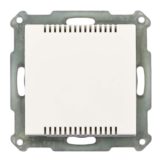
surface‐mounted flush‐mounted SCN‐RT1UP.01 SCN‐RT1APE.01 SCN‐RT1UPD.01 The room temperature sensor, SCN‐TS1UP.01, is for flush‐mounting. It contains also of a bus‐ connection, a programming button and a programming LED. MDT technologies GmbH • 51766 Engelskirchen • Papiermühle 1 Tel.: +49-2263-880 • Fax: +49-2263-4588 • knx@mdt.de • www.mdt.de... -
Page 6: Functions
All sensors contain of an in‐plant balance. Alarm/Messages Alarms and messages can be adjusted at this menu. This alarms and messages report when the temperature falls below an adjusted value or exceed an adjusted value. Controller general At this menu, the desired function (heating, cooling or heating & cooling) can be assigned and general settings, like setpoints, can be adjusted. Controller settings This menu appears as soon as the controller has got a function assigned. Integrated controllers can be chosen at this menu and the chosen controller can be parameterized further. If you choose the SCN‐TS1UP.01 as device at the setup general, only the menus setup general, temperature measurement and alarm/messages will be shown. MDT technologies GmbH • 51766 Engelskirchen • Papiermühle 1 Tel.: +49-2263-880 • Fax: +49-2263-4588 • knx@mdt.de • www.mdt.de... -
Page 7: Overview Functions
Reference point of the temperature control Setpoints Reference points for operating modes and controller modes parameterize able Shift of setpoints Max. shift parameterize able Scope of the shift parameterize able can be saved Blocking objects can be used for heating and cooling separately Guiding can be switched on/off Min/Max Values parameterize able impact to setpoint parameterize able MDT technologies GmbH • 51766 Engelskirchen • Papiermühle 1 Tel.: +49-2263-880 • Fax: +49-2263-4588 • knx@mdt.de • www.mdt.de... -
Page 8: Settings At The Ets-Software
2.7 Starting up After wiring the allocation of the physical address and the parameterization of every channel follow: (1) Connect the interface with the bus, e.g. MDT USB interface (2) set bus power up (3) Press the programming button at the device(red programming LED lights) (4) Loading of the physical address out of the ETS‐Software by using the interface(red LED goes out, as well this process was completed successful) (5) Loading of the application, with requested parameterization (6) Switch the power supply on (7) If the device is enabled you can test the requested functions(also possible by using the ETS‐ Software) MDT technologies GmbH • 51766 Engelskirchen • Papiermühle 1 Tel.: +49-2263-880 • Fax: +49-2263-4588 • knx@mdt.de • www.mdt.de... -
Page 9: 3 Communication Objects
X X 18 Cooling request Send request 1 Bit Low X X 19 Heating/Cooling 0=Heating 1 Bit Low X X switchover 1=Cooling MDT technologies GmbH • 51766 Engelskirchen • Papiermühle 1 Tel.: +49-2263-880 • Fax: +49-2263-4588 • knx@mdt.de • www.mdt.de... - Page 10 Send controller status 2 Byte Low X X 31 Mode selection Select mode 1 Byte Low X Chart 2: Communication objects – default settings You can see the default values for the communication objects from the upper chart. According to requirements the priority of the particular communication objects as well as the flags can be adjusted by the user. The flags allocates the function of the objects in the programming thereby stands C for communication, R for Read, W for write, T for transmit and U for update. * from version 1.2 MDT technologies GmbH • 51766 Engelskirchen • Papiermühle 1 Tel.: +49-2263-880 • Fax: +49-2263-4588 • knx@mdt.de • www.mdt.de...
-
Page 11: 4 Reference Ets-Parameter
Adjustment of the used device SCN‐RTxPE.xx with setwheel SCN‐RTxPD.xx with display SCN‐TS1UP.01 without controller function Chart 3: General settings The parameter startup timeout adjusts the time between an upload and the functional start of the device. The used hardware reacts only after expiration of the adjusted time. All input commands before the startup timeout expire. Additional, you have to select the used hardware at this menu. There are additional settings at the devices with setwheel and display. These settings are described at the following segments. The SCN‐TS1UP.01 is a pure temperature sensor, which does not contain of any controller functions. When this hardware is selected, only the menus “Setup general“(4.1), “Temperature measurement” (4.2) and “Alarm/Messages” (4.3) are shown and can be parameterized. MDT technologies GmbH • 51766 Engelskirchen • Papiermühle 1 Tel.: +49-2263-880 • Fax: +49-2263-4588 • knx@mdt.de • www.mdt.de... -
Page 12: Room Temperature Controller With Setwheel
Technical Manual Room Temperature Controller SCN‐RT1 4.1.1 Room Temperature Controller with setwheel The following settings are available at the ETS‐Software: Illustration 6: Additional settings controller with setwheel As well as the function „Setpoint offset with setwheel“ is activated, the communication object number 7 “manual setpoint value offset”(have a look at 4.4.3 ) disappears. 4.1.2 Room Temperature Controller with display The following settings are available at the ETS‐Software: Illustration 7: Additional settings with display MDT technologies GmbH • 51766 Engelskirchen • Papiermühle 1 Tel.: +49-2263-880 • Fax: +49-2263-4588 • knx@mdt.de • www.mdt.de... - Page 13 There are two possible functions, which can be assigned to the left keys. On the one hand, you can send the state whether a person is in the room or not. By sending the telegram “absent”, the temperature controller switches automatically over to the standby mode. The telegram “present” causes a switch over to the comfort mode. On the other hand, you can control ventilation by the left keys. The backlight can be switched permanent on or permanent off. Furthermore it can be switched by an external communication object. The polarity of the communication object can be chosen by the settings. The chart shows the relevant communication object for switching the LCD backlight by an external communication object: Number Name Length Usage 27 LCD backlight 1 Bit Controlling of the LCD backlight Chart 5: Communication object LCD backlight extern MDT technologies GmbH • 51766 Engelskirchen • Papiermühle 1 Tel.: +49-2263-880 • Fax: +49-2263-4588 • knx@mdt.de • www.mdt.de...
-
Page 14: Temperature Measurement
Correction of the internal sensor (value*0,1K) [0] 100% intern Internal/external sensor Adjustment of the balance between 90% intern/ 10% extern internal and external sensor 80 % intern/ 20% extern … 100% extern Chart 6: Parameter Temperature measurement The effects of the settings are described at the following page. MDT technologies GmbH • 51766 Engelskirchen • Papiermühle 1 Tel.: +49-2263-880 • Fax: +49-2263-4588 • knx@mdt.de • www.mdt.de... - Page 15 The communication objects for an activated external sensor are shown at the chart: Number Name Length Usage 5 External sensor 2 Byte sends the measured temperature value of the external sensor 28 Error external sensor 1 Bit sends an error, when the external sensor sends no value for more than 30min Chart 9: Communication objects external sensor MDT technologies GmbH • 51766 Engelskirchen • Papiermühle 1 Tel.: +49-2263-880 • Fax: +49-2263-4588 • knx@mdt.de • www.mdt.de...
-
Page 16: Alarm/Messages
not active Messages Activation of the message function active Message if value > 18°C‐40°C Dynamic range of the upper message [26°C] Adjustment possible if messages are activated Message if value < 1°C‐25°C Dynamic range of the lower message [13°C] Adjustment possible if messages are activated Chart 10: Parameter Alarm/Messages MDT technologies GmbH • 51766 Engelskirchen • Papiermühle 1 Tel.: +49-2263-880 • Fax: +49-2263-4588 • knx@mdt.de • www.mdt.de... - Page 17 Number Name Length Usage 1 Higher message value 1 Bit Send the achievement of the higher reporting limit 2 Below message value 1 Bit Send the achievement of the lower reporting limit Chart 12: Communication objects messages MDT technologies GmbH • 51766 Engelskirchen • Papiermühle 1 Tel.: +49-2263-880 • Fax: +49-2263-4588 • knx@mdt.de • www.mdt.de...
-
Page 18: Controller General
[default value] Controller off Controller type Adjustment of the controller type Heating The further settings depent to the adjusted Cooling controller type Heating and Cooling Chart 13: Setting controller type The controller type defines the function of the room temperature controller. Target of the control is to keep an adjusted temperature constant. There are a lot of settings, which can help to achieve this aim. The settings depend to the adjusted controller type. By choosing the setting “controller off”, no further settings are possible. MDT technologies GmbH • 51766 Engelskirchen • Papiermühle 1 Tel.: +49-2263-880 • Fax: +49-2263-4588 • knx@mdt.de • www.mdt.de... -
Page 19: Operating Modes & Setpoints
0 K – 10,0 K mode was chosen [2,0 K] The lowering is relative to the basis comfort setpoint. Setpoint frost protection 3°C – 12°C Setpoint of the operating mode frost [7°C] protection. indicated by an absolute value Setpoint heat protection 24°C – 40°C Setpoint of the operating mode heat [35°C] protection. indicated by an absolute value Chart 14: Operating modes & setpoints MDT technologies GmbH • 51766 Engelskirchen • Papiermühle 1 Tel.: +49-2263-880 • Fax: +49-2263-4588 • knx@mdt.de • www.mdt.de... - Page 20 The chart shows the relevant 1‐Bit communication objects: Number Name Length Usage 13 Mode frost protection 1 Bit Activation of the operating mode frost protection 13 Mode heat protection 1 Bit Activation of the operating mode heat protection 13 Mode frost/heat protection 1 Bit Activation of the operating mode frost/heat protection Chart 17: Communication object operating mode frost/heat protection MDT technologies GmbH • 51766 Engelskirchen • Papiermühle 1 Tel.: +49-2263-880 • Fax: +49-2263-4588 • knx@mdt.de • www.mdt.de...
- Page 21 1 0 Night 0 0 1 Frost‐/Heat protection 0 0 0 Standby 1 0 1 Frost‐/Heat protection 1 1 0 Comfort Chart 19: Example changeover of the operating modes via 1 Bit MDT technologies GmbH • 51766 Engelskirchen • Papiermühle 1 Tel.: +49-2263-880 • Fax: +49-2263-4588 • knx@mdt.de • www.mdt.de...
- Page 22 4 5 Heating/Cooling 0=Cooling/1=Heating 0x20 6 7 Frost alarm 1=Frost alarm 0x80 Chart 22: Hex‐Values DPT HVAC Status (from Version 1.2) If you heat at the comfort mode, the communication object will send the value 20 (for heating) +1 (for the comfort mode) =21. MDT technologies GmbH • 51766 Engelskirchen • Papiermühle 1 Tel.: +49-2263-880 • Fax: +49-2263-4588 • knx@mdt.de • www.mdt.de...
- Page 23 Activation of the mode night 13 Mode Frost/Heat protection 1 Bit Activation of the mode Frost/ Heat protection 25 DPT_HVAC Status* 1 Byte Visualization of the chosen operating mode 30 DPT_RHCC Status* 2 Byte Visualization measuring/ status of the controller 31 mode selection* 1 Byte Selection of the operating mode Chart 24: Communication objects for the operating mode changeover * from Version 1.2 MDT technologies GmbH • 51766 Engelskirchen • Papiermühle 1 Tel.: +49-2263-880 • Fax: +49-2263-4588 • knx@mdt.de • www.mdt.de...
- Page 24 The following settings are available at the ETS‐Software: Illustration 13: Operating mode after reset The following chart shows the dynamic range for this parameter: ETS‐text Dynamic range comment [default value] Comfort Operating mode after reset Adjustment, which operating mode shall Standby be switched on after a bus power return Chart 25: Operating mode after reset This parameter defines the operating mode, which shall be adjusted after a bus power return. The controller can start with the comfort mode or with the standby mode. MDT technologies GmbH • 51766 Engelskirchen • Papiermühle 1 Tel.: +49-2263-880 • Fax: +49-2263-4588 • knx@mdt.de • www.mdt.de...
-
Page 25: Setpoint Offset
No Send setpoint change Adjustment, whether a change of mode Yes should be send or not Chart 26: Setpoint offset The setpoint can be changed manual by the setpoint offset without a new parameterization by the ETS‐Software. Therefore, 2 variants are available. On the one hand a new setpoint can be pretended by the communication object “Setpoint comfort”. On the other hand the adjusted setpoint can be increased or decreased manual by the communication object “manual setpoint value offset”. At the read in of a new absolute comfort setpoint, the controller becomes a new basis comfort setpoint. The new basic comfort setpoint causes also an adaption of the indirect setpoints at the other operating modes. Through this function it is for example possible to read the actual room temperature as new basic comfort setpoint in. The settings “max setpoint offset”, “max setpoint offset valid for” and “Reset setpoint offset after change of mode” are not valid at this variant of setpoint offset, because the controller becomes a complete new setpoint. Specifying a new value is possible by calling the object “Setpoint comfort”. MDT technologies GmbH • 51766 Engelskirchen • Papiermühle 1 Tel.: +49-2263-880 • Fax: +49-2263-4588 • knx@mdt.de • www.mdt.de... - Page 26 Name Length Usage 6 Setpoint comfort 2 Byte Parameterization of a new absolute comfort setpoint 7 Manual setpoint value offset 2 Byte Movement of the setpoint depending to the current adjusted basic comfort setpoint 29 Actual setpoint 2 Byte Readout of the actual adjusted setpoint Chart 27: Communication objects setpoint offset MDT technologies GmbH • 51766 Engelskirchen • Papiermühle 1 Tel.: +49-2263-880 • Fax: +49-2263-4588 • knx@mdt.de • www.mdt.de...
-
Page 27: Blocking Objects
The blocking objects have the size of 1 Bit and blocks by sending a logical 1 at the depending communication object. The chart shows the relevant communication objects: Number Name Length Usage 14 Heating disable object 1 Bit blocks the control value heating 15 Cooling disable object 1 Bit blocks the control value cooling Chart 29: Communication objects blocking objects MDT technologies GmbH • 51766 Engelskirchen • Papiermühle 1 Tel.: +49-2263-880 • Fax: +49-2263-4588 • knx@mdt.de • www.mdt.de... -
Page 28: Heating/Cooling Request Objects
The objects can be used for the visualization of a beginning or ending heating/cooling process. So, for example, a red LED could show a heating process and a blue LED a cooling process. A further opportunity for the usage is the central switch of a heating or cooling process. So can be realized that all heating devices of a building switch on, when a controller gives out a heating request. The 1 Bit communication object gives as long a 1‐signal out as the process is active. The following chart shows the relevant communication objects: Number Name Length Usage 17 Heating request 1 Bit indicates a beginning heating process 18 Cooling request 1 Bit indicates a beginning cooling process Chart 31: Communication objects heating/cooling request MDT technologies GmbH • 51766 Engelskirchen • Papiermühle 1 Tel.: +49-2263-880 • Fax: +49-2263-4588 • knx@mdt.de • www.mdt.de... -
Page 29: Guiding
)/(w ‐ w max max min If the guiding shall cause an increment of the setpoint, you have to adjust a positive value for the setting “Setpoint variation at maximum guiding value”. If you wish a decrement of the setpoint, you have to choose negative value for the setting “Setpoint variation at maximum guiding value”. The variation of the setpoint X is added to the basic comfort setpoint. A measured temperature value for the guiding above the adjusted maximum value or below the adjusted minimum value has no effect to the setpoint. So when the value is between the adjusted guiding values (w & w the setpoint is increased or max decreased. MDT technologies GmbH • 51766 Engelskirchen • Papiermühle 1 Tel.: +49-2263-880 • Fax: +49-2263-4588 • knx@mdt.de • www.mdt.de... - Page 30 The following settings must be done at the controller: Basics Comfort setpoint: 22°C Guiding: active Guising value minimum: 28 °C Guiding value maximum: 38°C Setpoint variation at maximum guiding value: 10°C If the temperature outside increase to value of 32°C now, the setpoint will be increased by the following value: X = 10°C * [(32°C‐28°C)/(38°C–28°C)] = 4°C So we would have a new setpoint of 22°C+4°C = 26°C. If the outside temperature reaches the adjusted maximum of 38°C, the setpoint will be 32°C and behave this value even if the temperature would continue to rise. MDT technologies GmbH • 51766 Engelskirchen • Papiermühle 1 Tel.: +49-2263-880 • Fax: +49-2263-4588 • knx@mdt.de • www.mdt.de...
-
Page 31: Dead Zone
Dead zone between heating 1,0K – 10,0K Dynamic range for the dead zone and cooling (K) [2,0K] (Range at which the controller does not activate cooling or heating) Chart 34: Dead zone The settings for the dead zone are only available, when the controller type (have a look at 4.4.1 controller type) was set as heating and cooling. Now the dead zone can be parameterized. The dead zone describes the range at which the controller neither heats nor cools. So the controller sends no value to the control value, when he is in the dead zone. At the setting for the dead zone, it is to note, that a value which was chosen too small causes many switches between heating and cooling. Whereas, a too big chosen value causes a wide range of the current room temperature. When the controller is set as heating and cooling, the basic comfort setpoint is always the setpoint for heating. The setpoint for the cooling is given by the summation of basic comfort setpoint and dead zone. So, when the basic comfort setpoint is set to 21°C and the dead zone is set to 3K, the setpoint for heating is 21°C and the setpoint for cooling is 24°C. MDT technologies GmbH • 51766 Engelskirchen • Papiermühle 1 Tel.: +49-2263-880 • Fax: +49-2263-4588 • knx@mdt.de • www.mdt.de... - Page 32 Technical Manual Room Temperature Controller SCN‐RT1 The dependent setpoints for heating and cooling, so the setpoints for the operating modes standby and night, can be parameterized individually at the controller type heating and cooling. So you can set different values for the nigh and standby reduction/increase at heating and cooling. These setpoints are calculated in dependence to the basic comfort setpoints. The setpoints for the frost and heat protection are individually from the dead zone and the other setpoints. The following illustration shows the correlations between dead zone and the setpoints for the single operating modes. The following settings are made for this example: Basic comfort setpoint: 21°C Dead zone between heating and cooling: 3K Increase and Reduction standby: 2K Increase and Reduction night: 4K Illustration 21: Example dead zone MDT technologies GmbH • 51766 Engelskirchen • Papiermühle 1 Tel.: +49-2263-880 • Fax: +49-2263-4588 • knx@mdt.de • www.mdt.de...
-
Page 33: Controller Settings
1 Bit 8 Control value heating/cooling 1 Byte/ controlling of the combined actuator for 1 Bit heating and cooling 10 Control value cooling 1 Byte/ controlling of the actuator for cooling 1 Bit Chart 36: Communication objects control value According to the adjusted controller type (4.4.1), the control value controls a heating and/or a cooling process. If the control value is chosen as PI control continuous, the communication objects will have the size of 1 Byte, because the object can assume several states. If the control value is chosen as PI control switching or 2‐step control, the communication object will have the size of 1 Bit, because the communication object can only assume the states on or off. MDT technologies GmbH • 51766 Engelskirchen • Papiermühle 1 Tel.: +49-2263-880 • Fax: +49-2263-4588 • knx@mdt.de • www.mdt.de... -
Page 34: Direction Ofcontroller
By choosing heating/cooling system as [150 min] “Adjustment via control parameter”, the reset time can be parameterized freely Send control value cyclic Disable, 1 min, 2min, 3min, 4 min, Activation of cyclic sending of the 5min, 10min, 15min, 20min, 30min, control value with adjustment of the 40min, 50min, 60min cyclic time [Disable] No Use additional level Activation of an additional level Yes available, only for heating (4.5.6) Chart 37: PI control continuous MDT technologies GmbH • 51766 Engelskirchen • Papiermühle 1 Tel.: +49-2263-880 • Fax: +49-2263-4588 • knx@mdt.de • www.mdt.de... - Page 35 4.5.2.3 Proportional range The proportional range describes the P‐amount of the controlling. The P‐amount produces a proportional increment to the deviation of the control value. A small proportional range causes a short recovery time of the deviation. The controller reacts thereby almost immediately and sets the control value already at a small deviation almost to the maximum value (=100%). If the proportional range is chosen too small, the system will swing across. The following setting rules can be defined: small proportional range: swing across possible at change of setpoint; usage at fast systems; small recovery times big proportional range: almost no danger of swing across; long recovery times, usage at slow systems which need huge amplifications (big heating power etc.) MDT technologies GmbH • 51766 Engelskirchen • Papiermühle 1 Tel.: +49-2263-880 • Fax: +49-2263-4588 • knx@mdt.de • www.mdt.de...
- Page 36 To note is, that a reset time, which is adjusted too small, can cause across swinging. In principle you can say each carrier the system, each bigger the reset time. The following setting rules can be defined: small reset time: fast regulating of deviations; usage at fast systems and at places with changing environmental conditions (disturbance variables like draft); danger of swinging across big reset time: slow regulating of deviations; almost no danger for swinging across; usage at slow systems as underfloor heating 4.6.2.5 Send control value cyclic The parameter “Send control value cyclic” causes a cyclic sending of the actual control value. The time shifts between two values can be also parameterized. MDT technologies GmbH • 51766 Engelskirchen • Papiermühle 1 Tel.: +49-2263-880 • Fax: +49-2263-4588 • knx@mdt.de • www.mdt.de...
- Page 37 100%; 90%; 80%; 75%; 70%; 60%; indicates the output power at maximum 50%; 40%; 30%; 25%; 20%; 10%; 0% amount [100%] Warm water heating (5K/150 Heating system Adjustment of the used heating system min) Individual parameterization available by Underfloor heating (5K/240 “Adjustment via control parameter” min) Split Unit (4K/90min) Adjustment via control parameter MDT technologies GmbH • 51766 Engelskirchen • Papiermühle 1 Tel.: +49-2263-880 • Fax: +49-2263-4588 • knx@mdt.de • www.mdt.de...
- Page 38 [10min] Chart 38: PI control switching (PWM) At the pulse width modulation, the controller switches the control value according to the calculated value of the continuous control on and off. Thereby the control watches also the adjusted cycletime. So the control value is converted to a pulse width modulation with only the two conditions “0” and “1”. 4.5.3.1 PWM cycletime The cycletime, „PWM cycletime“, serves the controlling for calculating the length of the on‐pulse and the off‐pulse. This calculation occurs at the base of the calculated continuous value in percent. One PWM cycle contains the time, which elapses from one switching on point to the other. Example: If a control value of 75% is calculated and a cycletime of 10min is adjusted, the control value will be switched on for 7,5min and switched off for 2,5min. In principle you can say each carrier the system, each bigger the cycletime. MDT technologies GmbH • 51766 Engelskirchen • Papiermühle 1 Tel.: +49-2263-880 • Fax: +49-2263-4588 • knx@mdt.de • www.mdt.de...
- Page 39 [2,0K] the switching on point No Use additional level Activation of an additional level Yes possible, only for heating (4.5.6) Chart 39: 2‐step control (switching) The 2‐step control is the easiest way of controlling. The controller switches the control value only on and off. The controller switches the control value (for example at heating) on, when the measured temperature falls below a certain temperature. By exceeding a certain temperature, the control value will be switched off again. The points for switching on and off depend to the current adjusted setpoint and the adjusted hysteresis. The 2‐step control is used in situations, where the control value can only have two conditions and the controlled temperature can alternate a bit more. MDT technologies GmbH • 51766 Engelskirchen • Papiermühle 1 Tel.: +49-2263-880 • Fax: +49-2263-4588 • knx@mdt.de • www.mdt.de...
- Page 40 Technical Manual Room Temperature Controller SCN‐RT1 4.5.4.1 Hysteresis The setting of the hysteresis is used for calculating the points of switching on and off. This occurs under consideration of the current adjusted setpoint. Example: The controller is adjusted as heating with and a basic comfort setpoint of 21°C and a hysteresis of 2K. So the controller switches the control value, at the mode comfort, on at 20°C and off at 22°C. To note is that a big hysteresis generates big differences of the room temperature. A small hysteresis can generate an almost permanent switching process, because the points for switching on and off are very close to each other. This can generate a fast consumption of the control value. MDT technologies GmbH • 51766 Engelskirchen • Papiermühle 1 Tel.: +49-2263-880 • Fax: +49-2263-4588 • knx@mdt.de • www.mdt.de...
-
Page 41: Additional Level
PI‐control continuous The control value falls at raising regular difference and rises at falling regular difference. PI‐control switching The ratio between duration of switching on to the whole PWM cycletime raise by falling temperature and falls by raising temperature. 2‐Step control The controller switches on at the normal point for switching off and switches off at the normal point for switching on. 4.5.6 Additional level The following settings are available at the ETS‐Software: Illustration 27: Additional level MDT technologies GmbH • 51766 Engelskirchen • Papiermühle 1 Tel.: +49-2263-880 • Fax: +49-2263-4588 • knx@mdt.de • www.mdt.de... - Page 42 Example: The controller has the operating mode comfort, with the basic comfort setpoint of 21°C. The distance is adjusted as 2,0K. So the setpoint for the additional level is 21°C‐ 2,0K=19,0°C. An additional level can be used at carry systems to reduce the warm up time. For example can a radiator be used as additional level for reducing the war up time of an underfloor heating. The following chart shows the relevant communication object: Number Name Length Usage 9 Control value additional 1 Bit control value for the additional level heating Chart 41: Communication object additional level MDT technologies GmbH • 51766 Engelskirchen • Papiermühle 1 Tel.: +49-2263-880 • Fax: +49-2263-4588 • knx@mdt.de • www.mdt.de...
- Page 43 Technical Manual Room Temperature Controller SCN‐RT1 The following illustration shows the combination of the basic level and the additional level: Illustration 28: Combination of basic and additional level MDT technologies GmbH • 51766 Engelskirchen • Papiermühle 1 Tel.: +49-2263-880 • Fax: +49-2263-4588 • knx@mdt.de • www.mdt.de...
-
Page 44: Additional Settings For Heating And Cooling
4 Pipe system and cooling circuits automatically Heating/cooling switch Selection between manual and via object over automatic switch over Chart 42: Heating & Cooling When the controller type (4.4.1) is chosen as heating and cooling, the upper shown settings are available. By the setting for the system, the used system can be chosen. When a combined heating and cooling system is used, the setting 2 Pipe system must be chosen. When a divided system for heating and cooling is used, the setting 4 Pipe system must be chosen. Furthermore it is possible to choose between an automatic and a manual switch over. MDT technologies GmbH • 51766 Engelskirchen • Papiermühle 1 Tel.: +49-2263-880 • Fax: +49-2263-4588 • knx@mdt.de • www.mdt.de... - Page 45 Technical Manual Room Temperature Controller SCN‐RT1 4.5.7.1 ‐ 2 Pipe system At a common pipe system for heating and cooling, only one communication object for the control value is available. Before changing between heating and cooling, a switchover must occur. The control value can also have only one controller (PI‐continuous, PI‐switching, 2‐Step control). Also the direction must be identical for heating and cooling. But the parameter for the heating and cooling process can be defined individually (as described from 4.5.2 to 4.5.4). The following illustration shows the setting option for a 2 Pipe system: Illustration 30: 2 Pipe system MDT technologies GmbH • 51766 Engelskirchen • Papiermühle 1 Tel.: +49-2263-880 • Fax: +49-2263-4588 • knx@mdt.de • www.mdt.de...
- Page 46 Technical Manual Room Temperature Controller SCN‐RT1 4.5.7.2 ‐ 4 Pipe system When a divided pipe system is used, both operations can be parameterized individually. Consequently two communication objects for the control value exist. So it is possible, to control the heating process e.g. via a PI‐control continuous and the cooling process e.g. via a 2‐step control, because both processes are controlled by different devices. So for every of the both processes are the settings available, which are described from “4.5 controller settings”. The following illustration shows the setting options for a 4 Pipe system: Illustration 31: 4 Pipe system MDT technologies GmbH • 51766 Engelskirchen • Papiermühle 1 Tel.: +49-2263-880 • Fax: +49-2263-4588 • knx@mdt.de • www.mdt.de...
- Page 47 By choosing the switchover via object, an additional communication object is shown. By this object the switchover can be done. The controller stays as long at the adjusted operating mode until it becomes a signal via the according communication object. As long as the controller is at the heating mode only the setpoint for the heating is watched, also if the controller is, according to its setpoints, already at the cooling mode. A start of the cooling mode is also only possible, when the controller becomes a signal via the communication object. A “0” switches the heating process on and a “1” switches the cooling process on. The following chart shows the relevant communication object: Number Name Length Usage 19 Heating/Cooling switchover 1 Bit Switchover between heating and cooling 0=heating; 1=cooling Chart 43: Communication object heating and cooling MDT technologies GmbH • 51766 Engelskirchen • Papiermühle 1 Tel.: +49-2263-880 • Fax: +49-2263-4588 • knx@mdt.de • www.mdt.de...
- Page 48 Page 44 Illustration 30: 2 Pipe system Page 45 Illustration 31: 4 Pipe system Page 46 MDT technologies GmbH • 51766 Engelskirchen • Papiermühle 1 Tel.: +49-2263-880 • Fax: +49-2263-4588 • knx@mdt.de • www.mdt.de...
- Page 49 Page 42 Chart 42: Heating & Cooling Page 44 Chart 43: Communication object heating and cooling Page 47 MDT technologies GmbH • 51766 Engelskirchen • Papiermühle 1 Tel.: +49-2263-880 • Fax: +49-2263-4588 • knx@mdt.de • www.mdt.de...
-
Page 50: 6 Attachment
The above‐described devices must not be used with devices, which serve directly or indirectly the purpose of human, health‐ or lifesaving. Further the devices must not be used if their usage can occur danger for humans, animals or material assets. Do not let the packaging lying around careless, plastic foil/ ‐bags etc. can be a dangerous toy for kids. 6.2 Routine disposal Do not throw the waste equipment in the household rubbish. The device contains electrical devices, which must be disposed as electronic scrap. The casing contains of recyclable synthetic material. 6.3 Assemblage Risk for life of electrical power! All activities on the device should only be done by an electrical specialist. The county specific regulations and the applicable EIB‐directives have to be observed. MDT technologies GmbH • 51766 Engelskirchen • Papiermühle 1 Tel.: +49-2263-880 • Fax: +49-2263-4588 • knx@mdt.de • www.mdt.de... -
Page 51: Controller
Technical Manual Room Temperature Controller SCN‐RT1 6.4 Controller Three different controller types can be chosen for the control value. These controller types are described for the heating process by the following illustrations. 6.4.1 2‐Step control MDT technologies GmbH • 51766 Engelskirchen • Papiermühle 1 Tel.: +49-2263-880 • Fax: +49-2263-4588 • knx@mdt.de • www.mdt.de... - Page 52 Technical Manual Room Temperature Controller SCN‐RT1 6.4.2 PI‐control continuous MDT technologies GmbH • 51766 Engelskirchen • Papiermühle 1 Tel.: +49-2263-880 • Fax: +49-2263-4588 • knx@mdt.de • www.mdt.de...
-
Page 53: Pi-Control Switching (Pwm)
Technical Manual Room Temperature Controller SCN‐RT1 6.4.3 PI‐control switching (PWM) MDT technologies GmbH • 51766 Engelskirchen • Papiermühle 1 Tel.: +49-2263-880 • Fax: +49-2263-4588 • knx@mdt.de • www.mdt.de... -
Page 54: Direction Of Controller
Technical Manual Room Temperature Controller SCN‐RT1 6.5 Direction of controller MDT technologies GmbH • 51766 Engelskirchen • Papiermühle 1 Tel.: +49-2263-880 • Fax: +49-2263-4588 • knx@mdt.de • www.mdt.de... - Page 55 • HVAC object and 1bit object to choose operation mode • RHCC status and bit/byte objects to declare status • Installation with enclosed support ring, integrated bus coupling unit • 3 years warranty DIN EN ISO 9001 MDT technologies GmbH 51766 Engelskirchen Papiermühle 1 • • TAW Cert Tel.: + 49 - 2263 - 880...
- Page 56 Dimensions UP/AP (W x H x D) x 13mm x 13mm x 26mm x 26mm Examplary circuit diagram SCN-RT1UPE.01 DIN EN ISO 9001 MDT technologies GmbH 51766 Engelskirchen Papiermühle 1 • • TAW Cert Tel.: + 49 - 2263 - 880 Fax: + 49 - 2263 - 4588 knx@mdt.de...
Need help?
Do you have a question about the KNX SCN-RT1UP.01 and is the answer not in the manual?
Questions and answers