Table of Contents
Advertisement
Quick Links
OWNER'S
MANUAL
MODEL NO.
390.2532
CAUTION:
Read and Follow
All Safety Rules and
Operating Instructions
Before First Use of
This Product.
Save This Manual For
Future Reference.
Sears, Roebuck and Co., Hoffman Estates, IL 60179 U.S.A.
PRINTED IN U.S.A.
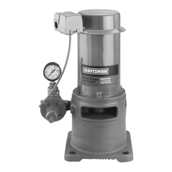
MULTI-STAGE JET PUMP
• Safety Instructions
• Installation
• Electrical
• Operation
• Maintenance
• Repair Parts
®
Form No.
F642-04077
(8/6/04)
Advertisement
Table of Contents

Related Manuals for Sears CRAFTSMAN 390.2532


Summary of Contents for Sears CRAFTSMAN 390.2532
- Page 1 • Safety Instructions Before First Use of • Installation This Product. • Electrical Save This Manual For • Operation Future Reference. • Maintenance • Repair Parts Sears, Roebuck and Co., Hoffman Estates, IL 60179 U.S.A. PRINTED IN U.S.A. F642-04077 Form No. (8/6/04)
-
Page 2: Table Of Contents
® WELL PUMP For one year from the date of purchase, Sears will repair or replace this pump, free of charge, if defective in material or workmanship. This warranty does not cover repairs or replacement parts necessary because of abuse or negligence including failure to install, adjust and operate this pump according to the instructions in the owner’s manual. -
Page 3: Major Components
AVC. An annual sure. Install a relief valve (Sears Stock No. 2729) set to check on the tank pre-charge pressure is recommended. -
Page 4: Pump Performance
* Jet Package No. 2967 – 2” Single Pipe (use 1-1/4” galvanized pipe). ** Jet Package No. 29902 – 3” Single Pipe (use 1-1/4” galvanized pipe). *** Jet Package No. 29660 – 4” Double Pipe. † Must be ordered through Sears Product Service, 1-800-366-7278. INSTALLATION Pipe Joint... -
Page 5: Installation
INSTALLATION NOTICE: For proper performance, pump MUST be Piping In The Deep Well matched to ejector and to well depth. Use this pump See Figures 6, 7, and 8. on wells 25’ to 210’ deep. NOTICE: Deep well installations are either single pipe 1. - Page 6 INSTALLATION 6. Thread a 1” plastic pipe adapter or a 1” nipple into 12. Remove paper backing from adhesive gasket. Apply the 1” tapped hole in ejector body (see Figure 8). gasket to adapter flange, making sure that holes line 7.
- Page 7 Air Volume Control To Service 10 to 20 feet below the lowest water level with pump Sears Stock No. 2761 running, if possible, but always at least 5 feet above the bottom of the well (see Figure 9, Page 7).
-
Page 8: Electrical
PRESSURE TANK CONNECTION ELECTRICAL Precharged Tank Connection Disconnect power before working on When a precharged tank is used, no AVC is necessary. pump, motor, pressure switch, or wiring. See Figure 12 for typical precharged tank installation. A precharged tank contains a factory provided air Motor Switch Settings charge. - Page 9 ELECTRICAL To change to 115 volts: ranty. The supply voltage must be within ±10% of the motor nameplate voltage. 1. Make sure power is off. NOTICE: Dual-voltage motors are factory wired for 2. Pull the plug toward you. 230 volts. If necessary, reconnect the motor for 115 3.
-
Page 10: Operation
OPERATION Priming The Pump 2. Start Pump: Pressure should increase rapidly to 50 pounds per Burn hazard. NEVER run pump dry. square inch or more as ejector and pump prime. If Running pump without water may cause pump so, go to step 4, below. to overheat, damaging seal and possibly causing If pressure does not build to 50 PSI, repeat steps a, burns to persons handling pump. -
Page 11: Helpful Hints / Maintenance
OPERATION 4. Once unit has primed and pressure stabilized, HELPFUL HINTS / MAINTENANCE slowly open (turn counterclockwise - Figure 19A, regulator valve until pressure falters (pressure How To Handle A Gaseous Well gauge needle flutters; pump may become noisy - see In some areas well water contains gases which must be Figure 19B). - Page 12 MAINTENANCE Using the Compound Gauge Pump Diassembly If the pump or system seems to be operating ineffi- 1. Pull disconnect switch. Disconnect power lines ciently, the compound gauge can sometimes help de- from pressure switch. termine the problem. 2. Remove the two cap screws holding the pump to A compound gauge is a combination vacuum and pres- the flange adapter.
- Page 13 MAINTENANCE 8. Hold the motor shaft with pliers or vice grips 11. Remove the intermediate volute and slide the im- through the opening in the pump adapter. Unscrew peller spacer off of the shaft. the impeller nut off the end of the shaft (see Figure 12.
- Page 14 MAINTENANCE 4. Carefully slide the adapter over the shaft (see 9. Install the intermediate volute, aligning it with the Figure 27). Do not damage the shaft sealing surface; mark made before disassembly. Use the long cap it is highly polished and any slight scratches or nicks screws to check this alignment.
-
Page 15: Troubleshooting Guide
TROUBLESHOOTING CHART SYMPTOM POSSIBLE CAUSE(S) CORRECTIVE ACTION Motor will not run 1. Disconnect switch is off 1. Be sure switch is on 2. Fuse is blown 2. Replace fuse 3. Starting switch is defective 3. Replace starting switch 4. Wires at motor are loose, discon- 4. -
Page 16: Repair Parts
REPAIR PARTS Multi-Stage Jet Pump 1 0 0 1281 0994 Repair Parts List - Multi-Stage Jet Part Part Number Description J218-600C Motor L43-5C Connector U36-112ZP Locknut - 1/2” U217-1228 Pressure Switch U37-672P Switch Tube - 14-1/2” J212-24A Pressure Regulator Assembly L2-16A Adapter U30-75ZP... - Page 17 REPAIR PARTS Pressure Regulator 1 0 0 To Order Parts, Call Sears Product Service, 2080 1095 1-800-366-7278 Repair Parts List - Pressure Regulator Part Number Part Description J112-14 Pressure Regulator Body w/Seat U111-212T Barbed Fitting - Elbow J66-16 Valve Seat...
- Page 18 REPAIR PARTS Vertical Casing Adapters and Adapter Flanges To Order Parts, for Multi-Stage Jet Pump Call Sears Product Service, 1-800-366-7278 489 0194 Adapter Flange Casing Adapter Repair Parts List - Adapter Flange Part Number Part Description J20-12 Adapter Gasket J2-17B Adapter –...
- Page 19 REPAIR PARTS Jet Packages 2” and 3” Single Pipe Jets 4” Double Pipe Jets Suction Pipe: 1-1/4" Drive Pipe: 1" Well Seal Adapter Steel Nipple Coupling Adapter Well Casing Drop Pipe 1" Pipe Adapter 1361 1094 1320 1094 Repair Parts List – Jet Packages 1360 1094 2967 29902...
- Page 20 Maintenance Agreement or to inquire about an existing Agreement call 9 am - 5 pm, Monday-Saturday • Product Type 1-800-827-6655 • Model Number • Part Number • Part Description REPAIR SERVICES America's Repair Specialists Sears, Roebuck and Co., Hoffman Estates, IL 60179 U.S.A.
Need help?
Do you have a question about the CRAFTSMAN 390.2532 and is the answer not in the manual?
Questions and answers