Stellar Hearth Products GALAXY Series Installation And Operating Manual
Co-linear direct vent gas fireplaces four sided
Hide thumbs
Also See for GALAXY Series:
- Installation and operating manual (55 pages) ,
- Installation and operating manual (52 pages) ,
- Installation and operating manual (52 pages)
Table of Contents
Advertisement
Quick Links
www.stellarhearth.com
Custom Fireplace Program
Co-linear Direct Vent Gas Fireplaces
GALAXY SERIES - FOUR SIDED
Installation and Operating Manual
NG & Propane
WARNING: If the information in these instructions are not followed exactly, a fire or explosion may result
causing property damage, personal injury or loss of life.
— Do not store or use gasoline or other flammable vapors and liquids in the vicinity of this or any other
appliance.
WHAT TO DO IF YOU SMELL GAS
—
•
Do not try to light any appliance.
•
Do not touch any electrical switch; do not use any phone in your building.
•
Immediately call your gas supplier from a neighbor's phone. Follow the gas supplier's instructions.
•
If you cannot reach your gas supplier, call the fire department.
— Installation and service must be performed by a qualified installer, service agency or the gas supplier.
Stellar Hearth Products
TM
, a division of Hearth & Home Technologies
Installer:
Leave this manual with the appliance.
Consumer: Retain this manual for future reference.
®
- 16873 Fish Point Rd SE, Prior Lake, MN 55372 - (952) 224 - 4072
Page 1
Advertisement
Table of Contents

Related Manuals for Stellar Hearth Products GALAXY Series


Summary of Contents for Stellar Hearth Products GALAXY Series
- Page 1 Custom Fireplace Program Co-linear Direct Vent Gas Fireplaces GALAXY SERIES - FOUR SIDED Installation and Operating Manual NG & Propane Installer: Leave this manual with the appliance. Consumer: Retain this manual for future reference. WARNING: If the information in these instructions are not followed exactly, a fire or explosion may result causing property damage, personal injury or loss of life. — Do not store or use gasoline or other flammable vapors and liquids in the vicinity of this or any other appliance.
- Page 2 Page 2 INS_CUST UL REV E...
-
Page 3: Table Of Contents
TABLE OF CONTENTS Section Description Page Safety Information Venting - Continued A. Safety Icon Designations K. Vertical Terminations B. Important Safety Considerations L. Horizontal Cap Location & Clearances M. Horizontal Terminiation Commonwealth of Massachusetts Requirements N. Powervent & Air-intake Placement Clearances O. -
Page 4: Safety Information
1 - SAFETY INFORMATION This fireplace complies with ANSI Z21.50-2019/CSA 2.22-2019 Vented Gas Fireplaces and CAN/CSA P.4.1-15. Installation must conform with local building codes or in the absence of local building codes, with the National Fuel Gas Code, ANSIZ223.1/NFPA 54 - Current Edition, or the Natural or Propane Installation Code, CSAB149.1 A. SAFETY ICON DESIGNATIONS Various safety icons appear throughout this installation manual. Please familiarize yourself with the icons making sure you understand the serious consequences that may occur if ignored or of handling the products inappropriately. IMPORTANT NOTE HOT GLASS WARNING This indicates additional instructions that you should consider... -
Page 5: Commonwealth Of Massachusetts Requirements
2 - COMMONWEALTH OF MASSACHUSETTS REQUIREMENTS NOTE: THE FOLLOWING REQUIREMENTS REFERENCE VARIOUS MASSACHUSETTS AND NATIONAL CODES NOT CONTAINED IN THIS MANUAL. For all sidewall horizontally vented gas fueled equipment installed in every dwelling, building or structure used in whole or in part for residential purpos- es, including those owned or operated by the Commonwealth and where the side wall exhaust vent termination is less than (7) feet above finished grade in the area of the venting, including but not limited to decks and porches, the following requirements shall be satisfied: INSTALLATION OF CARBON MONOXIDE DETECTORS EXEMPTIONS... -
Page 6: Specifications
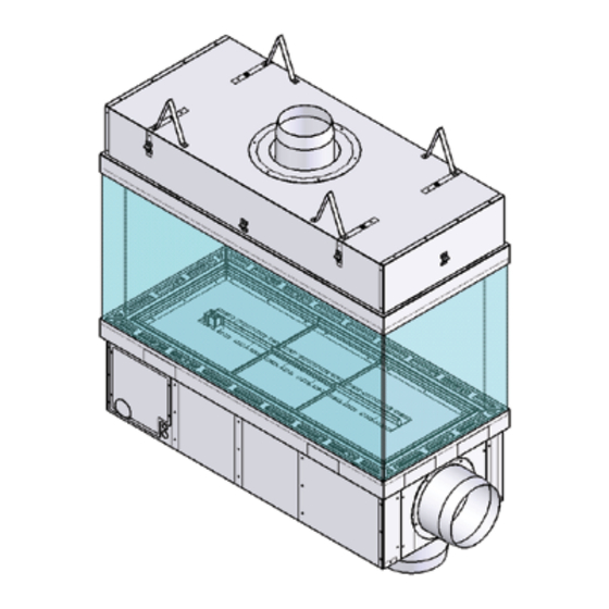
3 - SPECIFICATIONS FOUR SIDED DIMENSIONS: INCHES [MILLIMETERS] Finishing Finishing Firebox Top Overall Edge To Overall B-VENT AIR INTAKE Model # Glass Height Depth FLUE COLLAR Width - Front Width - Ends Height Height Center Flue Width Diameter Diameter 20" HIGH GLASS 41-3/4 20-7/8 41-3/4... - Page 7 3 - SPECIFICATIONS 3. FOUR SIDED DIMENSIONS 1/4-20 UNC 1/4-20 UNC B-VENT [305] [305] B-VENT TOP VIEW The hood shall be supported at specific locations using 1/4-20 UNC threaded rods. I, J & K You will find the dimensions for I, J & K in Section 3 (Prepare The Fireplace). [13] 3 [76] FRONT VIEW...
-
Page 8: Gas & Electric Access Dimensions (3', 4', 5', 6 & 7')
3 - SPECIFICATIONS B.3 GAS & ELECTRIC ACCESS LOCATIONS (3', 4', 5', 6' & 7') PILOT SIDE VIEW BACK SIDE VIEW ELECTRIC 3" GAS 3" GAS 2X 2 27/32" 1 1/2" 1 25/32" 1 1/2" 2X 1 19/32" 2 3/4" 2 7/32" 3 7/32" 5 3/8" 2 7/32" 11 1/8" ELECTRIC 2X 5 13/32"... -
Page 9: Gas & Electric Access Dimensions (8')
3 - SPECIFICATIONS B. 3 GAS & ELECTRIC ACCESS LOCATIONS (8') PILOT SIDE VIEW BACK SIDE VIEW ELECTRIC 3" GAS 3" GAS 2X 2 27/32" 2X 1 19/32" 2X 11 3/16" 1 25/32" 1 1/2" 1 11/16" 2X 2 7/32" 2 3/4" ELECTRIC 3 1/4" 5 13/32" 2X 2 7/32"... -
Page 10: Fireplace Specifications
3 - SPECIFICATIONS C. SPECIFICATIONS Propane Model # DESCRIPTION B-VENT REG PV IN-LINE PV BTU’S ORIFICE ORIFICE ANY HEIGHT 8" 10" RS012 RSIF160 40,000 (2X) #43 (2X) #55 ANY HEIGHT 8” 10” RS012 RSIF160 60,000 (3X) #43 (3X) #55 ANY HEIGHT 8”... -
Page 11: Clearances
3 - SPECIFICATIONS F. CLEARANCES From unit left & right sides 1" 25mm To flooring under fireplace Unit top to ceiling 6" 152mm Unit side to adjacent sidewall 1" 25mm CLEARANCES SHOWN ARE MINIMUM TO COMBUSTIBLES Figure 3F NON-COMBUSTIBLE FRAMING AND FINISHING MATERIALS ALLOWED RIGHT UP TO THE FIREPLACE. 1/2”... -
Page 12: Prepare The Fireplace
4 - PREPARE THE FIREPLACE CAUTION: FIREPLACE IS NOT LOAD-BEARING. NOTE: OTHER CLEARANCES APPLY. ALL CLEARANCES MUST BE MAINTAINED. A. STANDOFF INSTALLATION LOOSEN SCREW LOOSEN SCREW AND FOLD EACH AND FOLD EACH STANDOFF STANDOFF LOOSENED SCREW LOOSENED SCREW REMOVE REMOVE SECOND SCREW SECOND SCREW PIVOT FOLDED STANDOFF PIVOT FOLDED STANDOFF AND SECURE... -
Page 13: Shipping Support Brackets
4 - PREPARE THE FIREPLACE B. SHIPPING SUPPORT BRACKETS The hood must be supported at specific locations using 1/4-20 UNC threaded rods. Temporary support brackets are put in place for shipping and installation support and must stay in place until fireplace hood is fully supported. The temporary support brackets are not shipped in place on the Galaxy Four Sided Series and you will be required to assemble them at the jobsite to support the hood for installation. - Page 14 3 - PREPARE THE FIREPLACE B. SUPPORT BRACKET INSTALLATION STEP 1 STEP 1.1 Attach the four bottom brackets to the base in the STEP 1.2 Attach screws in this area to all four brackets. orientation shown. STEP 2 STEP 2.1 Attach cross beams as shown STEP 2.2 Attach screws on each side of the cross beam Page 14...
- Page 15 3 - PREPARE THE FIREPLACE B. SUPPORT BRACKET INSTALLATION STEP 3 STEP 3.1 Attach the four top brackets to the cross beams in the STEP 3.2 Attach screws on each side of the cross beam orientation shown STEP 4 STEP 4.1 Carefully place hood on top of the brackets.
-
Page 16: Threaded Rods
4 - PREPARE THE FIREPLACE C. THREADED RODS The Galaxy FOUR SIDED Series requires 4 threaded rods to be placed at the glass-to-glass intersections. Placement of the required threaded rods is at the I & J intersection at the front left and back FOUR SIDEDs notated as REQUIRED I & J locations. Additional locations are provided if your installation needs more support notated as OPTIONAL I, J &... -
Page 17: Threaded Rod Insallation (Example)
4 - PREPARE THE FIREPLACE D. THREADED RODS INSTALLATION (EXAMPLE) There are several different ways to support the fireplace top and one option is to use a Unistrut installed over the fireplace that is secured to structurally sound framing. Refer to Figure 4B. For each threaded rod installation you may need: Qty 1 Qty 1... -
Page 18: Framing & Mantel Requirements
5 - FRAMING NOTE: Framing dimensions should allow for wall covering thickness and fireplace facing materials. When using a hearth, adjust rough opening size as necessary to maintain at least minimum clearance requirements. CAUTION: Install fireplace on metal, concrete or hard wood surface extending the full width and depth of fireplace. CAUTION: Vent cap location must be in compliance with guidelines in Section 8 (Venting) of this manual. If masonry is to be used (optional), prepare the necessary foundation for the masonry load. When masonry construction is being used, a lintel must be used over top of fireplace to support the added weight. Build hearth to desired size and height. If a hearth extension is desired, combustible material may be used. -
Page 19: Framing Dimensions
5 - FRAMING A. FOUR SIDED FRAMING DIMENSIONS IMPORTANT:FIREPLACE IS NOT LOAD-BEARING. 6” [152] Dimensions assuming 1/2" hood standoffs are used. MINIMUM COMBUSTIBLE OR NON-COMBUSTIBLE NON-COMBUSTIBLE ZONE BACKING MATERIAL (I.E.SHEETROCK) OPEN AIR SPACE Framing Framing Framing INCHES [MM] Width Height Depth 40-3/4 34S-20GL [1,035] [1,321] [584] 52-3/4 44S-20GL [1,340] [1,321] [584]... -
Page 20: Mantel Requirements
5 - FRAMING (MANTEL REQUIREMENTS) B.1 NON-COMBUSTIBLE ZONE - USING THE PROVIDED 1/2" STANDOFFS The fireplace has standoffs installed on the front of the fireplace standard from the factory. They are located on the upper left, center and right front of the fireplace and are to ensure that the 1/2" [12.7mm] required clearance to combustibles on the surface of the fireplace is maintained. -
Page 21: Mantel Requirements
5 -FRAMING (MANTEL REQUIREMENTS) B.2 NON-COMBUSTIBLE ZONE - NOT USING THE PROVIDED 1/2" STANDOFFS The fireplace has standoffs installed on the front of the fireplace standard from the factory. They are located on the left, center and right front hood of the fireplace and are to ensure that the 1/2" [12.7mm] required clearance to combustibles on the surface of the fireplace is maintained. -
Page 22: Glass Frame Assembly
6 - GLASS FRAME ASSEMBLY A. GLASS FRAME ASSEMBLY IDENTIFICATION GLASS GLASS Upper Groove Quality Suction Cup LOWER FILLER STRIP SITS OVER GLASS CLIPS LOWER FILLER STRIP SITS OVER GLASS CLIPS Lower Groove GLASS CLIP GLASS CLIP Figure 6B.1 Figure 6A CAUTION: TO PREVENT GLASS FRAME ASSEMBLY FROM FALLING FROM FIREPLACE AND BECOMING DAMAGED, FOLLOW THE INSTRUCTIONS EXACTLY WHEN REMOVING AND INSTALLING GLASS FRAME ASSEMBLY. -
Page 23: Install Glass Frame Assembly/Glass Edge Protectors
6 - GLASS FRAME ASSEMBLY Refer to Section 6 (Glass Frame Assembly Identification Figures 6A & 6B.1) when installing and removing the glass frame assembly. B. INSTALL GLASS FRAME ASSEMBLY IMPORTANT: PLASTIC GLASS EDGE PROTECTORS The fireplace is shipped with a plastic edge protector on the outer pane of glass only. U-Shaped See Figure 6B.2 Edge Top/Bottom Glass Pane Protector Inner Glass Figure 6B.2 - Outer Glass Edge Protector Unwrap the panes of glass carefully making sure to protect the edges. -
Page 24: Gas Line Specifications & Connection
7 - GAS LINE SPECIFICATIONS This fireplace is manufactured for use with Natural Gas or Propane. CAUTION: Installation of the gas line must only be done by a qualified person in accordance with local building codes, if any. If not, follow ANSI 223.1. NOTE: The appliance and its individual shutoff valve must be disconnected from the gas supply piping system during any pressure testing of that system at pressures in excess of ½ psi. NOTE: The appliance must be isolated from the gas supply piping system by closing its individual manual shut-off valve during any pressure testing of the gas line at test pressures equal to or less than ½ psi (3.5 kPa). NOTE: For high altitude installations, consult Stellar Hearth Products directly for proper rating methods. GAS LINE CONNECTION Propane 11.0 inches W.C. 7.0 inches W.C. MINIMUM INLET GAS PRESSURE (recommended) (recommended) MAXIMUM INLET GAS PRESSURE 14.0 inches W.C. 10.0 inches W.C. MANIFOLD PRESSURE (HI) 10.0 inches W.C. -
Page 25: Venting
8 - VENTING CAUTION: Consult the local and national installation codes to assure adequate combustion and ventilation air is available. NOTE: Flame height and appearance will vary depending upon venting configuration and type of fuel used. Venting requirements apply to both Natural and Propane gas. STOP: MAINTAIN ALL CLEARANCES AS STATED IN THIS INSTALLATION MANUAL. Figure 7 A. APPROVED VENTING OUTSIDE STANDARD IN-LINE Model # DESCRIPTION B-VENT POWERVENT POWERVENTV ANY HEIGHT 8" 10" RS012 RSIF160 ANY HEIGHT 8” 10” RS012 RSIF160 ANY HEIGHT... -
Page 26: Rs Series Powervent Specifications
8 - VENTING D. RS SERIES POWERVENT SPECIFICATIONS Available Power Venting A power vent (RS-12 & RS014) is approved for use with this appliance. It is crucial that all B-Vent pipe and elbow joints, and the longitudinal seam are sealed using a high temperature RTV Silicone and/or foil tape. MODEL RS012 RS014... -
Page 27: Rsif Series Powervent Specifications
8 - VENTING F. RSIF SERIES POWERVENT SPECIFICATIONS Available In-Line Power Venting An in-line power vent (RSIF160 or RSIF180 is approved for use with this appliance. It is crucial that all B-Vent pipe and elbow joints, and the longitudi- nal seam are sealed using a high temperature RTV Silicone and/or foil tape. MODEL RSIF160 RSIF180... -
Page 28: In-Line Powervent Preparations - Rsif 180
D. IN-LINE POWERVENT PREPARATIONS G. IN-LINE POWERVENT PREPARATIONS- RSIF 180 Perform the following steps when installing the RSIF180 on 6', 7' & 8' models. 1. Attach the provided 10 inch B-Vent collar to the intake side of the powervent. The intake side is located opposite the fan motor as shown in Figure 8G.1. -
Page 29: Horizontal Vent System Clearance
8 - VENTING H. HORIZONTAL VENT SYSTEM CLEARANCES ALL APPROVED VENTING BOTTOM SIDES HORIZONTAL 1 inch [25mm] 1 inch [25mm] 1 inch [25mm] I. WALL PASS-THROUGH - Follow all local codes for requirement of firestops. 8 - VENTING J. PITOT TUBE INFORMATION Figure 8J There is a 1/4" pitot tube mounted in the center of the flue collar and is connected to the pressure switch. (Figure 8E) This monitors the pressure in the flue and is necessary for proper operation. -
Page 30: Vertical Terminations
8 - VENTING K. VERTICAL TERMINATIONS • The fireplace must terminate with the included approved powered termination cap. • NO SUBSTITUTION IS ACCEPTABLE. • Carefully follow the instructions included with the approved powered termination cap. DO NOT use an additional speed control on this powervent. • • You must use the included Capacitor. L. HORIZONTAL TERMINATION VENT CAP LOCATION & CLEARANCES This gas appliance must not be connected to a chimney serving any other appliance. • DO NOT RECESS TERMINATION KIT INTO OUTSIDE BUILDING MATERIALS - i.e.: brick, stone, siding, etc. If necessary, extend framing so that termination kit will be exposed once building materials are installed. - Page 31 8 - VENTING M. HORIZONTAL TERMINATION VENT CAP LOCATION & CLEARANCES Inside Corner Outside Corner Recessed Location A = Combustible 24” (609.6mm) F = Combustible 6” (152mm) = Non-combustible 6” (152mm) = Non-combustible 12” (304.8mm) Balcony Balcony with perpendicular side wall with no side wall C = Clearance from corner in recessed location = Combustible 24”...
- Page 32 8 - VENTING N. POWERVENT AND AIR-INTAKE PLACEMENT CLEARANCES RS SERIES POWERVENT IN-LINE POWERVENT (LOUVER 8/10) X = Intake X = Intake PV = Vent PV = Vent 0” P.V. 0” 0” 36” 24” 9” 9” 9” Minimum Clearance Using an In-Line Powevent Minimum Clearance Using a RS Series Powervent Intake Placed Below Vent = 24”...
- Page 33 8 - VENTING O. VERTICAL VENT CAP LOCATION AND CLEARANCES ROOF PITCH H (Min.) Ft. H (Min.) M. FLAT TO 6/12 1.0* 0.30 OVER 6/12 TO 7/12 1.25* 0.38 OVER 7/12 TO 8/12 1.5* 0.46 OVER 8/12 TO 9/12 2.0* 0.61 OVER 9/12 TO 10/12 2.5* 0.76 OVER 10/12 TO 11/12 3.25* 0.99 OVER 11/12 TO 12/12 1.22 OVER 12/12 TO 14/12 1.52 OVER 14/12 TO 16/12 1.83 OVER 16/12 TO 18/12 2.13 * = 3 foot minimum in OVER 18/12 TO 20/12 2.27...
- Page 34 8 - VENTING P. ROOF TERMINATION CAP INSTALLATION - WITH AND WITHOUT DAMPER Roof Termination Without Optional Mechanical Damper POWERVENT MOUNTING BRACKETS OR DRILL MOUNTING HOLES TO MATCH BASE INSULATION PAD MUST BE CUT IN CENTER TO ACCOMMODATE VENT SIZE STEEL CHIMNEY ADAPTER Figure 8P.1 Roof Termination With...
- Page 35 8 - VENTING Q. WALL TERMINATION - WITH AND WITHOUT DAMPER Wall Termination Without Optional Mechanical Damper FRAMING: 8" = 11-3/4" W X 11-3/4" H 10" = 13-1/4"" W X 13-1/4" H DRILL 1/4” HOLES TO MATCH POWER VENT BASE INSULATION PAD MUST BE CUT IN CENTER TO ACCOMMODATE VENT SIZE USE APPROPRIATE HEAVY DUTY FASTENERS TO SECURE POWER VENT Figure 8Q.1 Wall Termination With Optional Mechanical Damper...
- Page 36 8 - VENTING R. OUTDOOR AIR INTAKE This fireplace has the options of air intake connections on the side or the bottom of the fireplace. This fireplace is approved for use with 10 inch rigid metal pipe or UL approved 10 inch Class 0 or Class 1 flex for intake air. Use Table 8R.1 for venting requirements if using UL approved 10 inch flex for intake air.
- Page 37 8 - VENTING T. PDS-1 INSTALLATION (FOUR SIDED ONLY) NOTE: The four sided fireplace utilizes an external draft switch (PDS-1). This needs to be installed at the time the venting is installed. The installation instructions are included in the box with the PDS-1 kit. Please read fully prior to installation. Additional wiring information can be found on Page 35. Figure 8T.1 Figure 8T.2 PDS-1 Proven Draft Switch - Four Sided Fireplace Only Complete Installation Instructions Provided In The PDS-1 Box Figure 8T.4 Figure 8T.5 Figure 8T.3 Figure 8T.6 Page 37 16400-7806 G4S REV G...
- Page 38 9- VENTING OPTIONS OPTIONAL UNIVERSAL EXHAUST IN AIR-INTAKE LOUVER MODEL UNITS LOUVER-8 3', 4' & 5' Exhaust and Air-Intake LOUVER-10 6' & 7' Exhaust and Air-Intake LOUVER-12 Air-Intake ONLY This kit is an optional method of terminating the fresh air and/or exhaust for the appliance. Exhaust terminations must be installed with an FOLLOW COMPLETE inline powervent.
- Page 39 10- ELECTRIC A. ELECTRIC - AT INSTALL Powervent Figure 1A Voltage Chart RS012 RS014 RSIF160 RSIF180 13/16 Supply Voltage Chart (N/L1) RS012 To light the fireplace: Activate the switch. RS014 The fireplace has a pre and post timer, set at the factory for 30 seconds. RSIF160 The powervent will start after the switch is activated.
- Page 40 10- ELECTRIC B. ELECTRIC - SERVICE & TROUBLESHOOTING Figure 10B Page 40 INS_CUST UL REV E...
- Page 41 10 - ELECTRIC C.1 TERMINALS 1 & 2 - LED Lights Figure 10C.1 Terminals 1 & 2 C.2 TERMINALS 3 & 4 - Main Flame Figure 10C.2Terminals 3 & 4 Page 41 16400-7806 G4S REV G...
- Page 42 10 - ELECTRIC C.3 TERMINALS 5 & 6 - Fireplace Power GROUND - LOCATE THE GREEN WIRE CLUSTER CONNECT THE GREEN WIRE TAIL TO BUILDING GROUND Figure 10C.3 Terminals 5 & 6 C.4 TERMINALS 7 & 8 - Powervent Connection Figure 10C.4 Terminals 7 & 8 Page 42 INS_CUST UL REV E...
- Page 43 10 - ELECTRIC C.5 TERMINALS 9 & 10 - OPTIONAL Flue Damper Connection OPTIONAL Figure 10C.5 Terminals 9 & 10 TERMINALS 9 & 10 FLUE DAMPER CONNECTION TERMINAL #9 IS THE NEUTRAL CONNECTION FOR THE DAMPER MOTOR. BLACK WIRE TERMINAL #10 IS THE HOT CONNECTION FOR THE DAMPER MOTOR. RED WIRE THIS IS LOW VOLTAGE AND EXTERNAL POWER MUST NOT BE APPLIED 24 VAC DAMPER MOTOR - RED NEUTRAL DAMPER MOTOR - BLACK...
- Page 44 10 - ELECTRIC C.6 TERMINALS 11 & 12 - OPTIONAL Flue Damper Connection OPTIONAL Figure 10C.6 Terminals 11 & 12 NOTE: OPTIONAL IF A DAMPER IS NOT USED TERMINALS 11 AND 12 HAVE A JUMPER ACROSS THEM NOTE: RED IS NOT USED AND SHOULD BE SAFELY CAPPED Page 44 INS_CUST UL REV E...
- Page 45 10 - ELECTRIC C.7 TERMINALS 13 & 14 - 4S Only / Pressure Switch Figure 10C.7 Terminals 13 & 14 NOTE: YOU WILL NEED TO USE THE PSD-01 REMOTE LOCATED FLUE PRESSURE SWITCH. FOLLOW THE INSTRUCTIONS INCLUDED WITH THE SWITCH. Page 45 16400-7806 G4S REV G...
- Page 46 11 - FINISHING A.1 FINISHING THE WALL - USING THE PROVIDED 1/2" STANDOFFS NOTE: REFER TO DIMENSIONS SECTION FOR ALLOWABLE FINISHING DIMENSIONS REQUIRED TO FIT THE GLASS PANELS INTO THE FIREPLACE. FINISHING MATERIALS MUST NOT OVERLAP THE DIMENSIONS HIGHLIGHTED IN GREEN ON PAGE 5. NEVER COVER THE GLASS WITH FINISHING MATERIALS. NOTE: DO NOT FOUR SIDEDCE ANY OF THE BLACK PAINTED SURFACES WITH SCREWS, RIVETS, ETC. THIS INCLUDES THE 3" BLACK TOP AND BOTTOM GLASS TRIM AND ANY PAINTED SIDES ADJACENT TO THE GLASS. NOTE: REFER TO SECTION 5 MANTEL REQUIREMENTS: NON-COMBUSTIBLE ZONE USING PROVIDED 1/2" STANDOFFS FOR MORE INFORMATION.
- Page 47 11 - FINISHING A.2 FINISHING THE WALL - NOT USING THE PROVIDED 1/2" STANDOFFS NOTE: REFER TO DIMENSIONS SECTION FOR ALLOWABLE FINISHING DIMENSIONS REQUIRED TO FIT THE GLASS PANELS INTO THE FIREPLACE. FINISHING MATERIALS MUST NOT OVERLAP THE DIMENSIONS HIGHLIGHTED IN GREEN ON PAGE 5. NEVER COVER THE GLASS WITH FINISHING MATERIALS. NOTE: DO NOT FOUR SIDEDCE ANY OF THE BLACK PAINTED SURFACES WITH SCREWS, RIVETS, ETC. THIS INCLUDES THE 3" BLACK TOP AND BOTTOM GLASS TRIM AND ANY PAINTED SIDES ADJACENT TO THE GLASS. NOTE: REFER TO SECTION 5 MANTEL REQUIREMENTS: NON-COMBUSTIBLE ZONE USING PROVIDED 1/2" STANDOFFS FOR MORE INFORMATION.
- Page 48 12 - LIGHTING & SHUTDOWN FOR YOUR SAFETY - READ BEFORE LIGHTING STOP: IF YOU DO NOT FOLLOW THESE INSTRUCTIONS EXACTLY, A FIRE OR EXPLOSION MAY RESULT, CAUSING PROPERTY DAMAGE, PERSONAL INJURY OR LOSS OF LIFE. UE TO HIGH SURFACE TEMPERATURES, KEEP CHILDREN, CLOTHING AND FURNITURE AWAY. This appliance needs fresh air for safe operation and must be installed so there are provisions for adequate combustion and ventilation air. It is important to make sure the termination cap remains unobstructed at all times from snow, ice, leaves or other debris. •...
- Page 49 12 - LIGHTING & SHUTDOWN STOP! Read safety information on previous page and front cover of this manual before continuing. NOTE: This fireplace is equipped with an ignition device which automatically lights the pilot. DO NOT try to light the pilot by hand. B. IF THE FIREPLACE DOES NOT LIGHT Turn off the fireplace at switch. Turn off all electrical power to fireplace. Wait five (5) minutes to allow any gas that may have accumulated inside firebox to escape. If you then smell gas, STOP! Follow safety information on front cover and on previous page of the installation manual.
- Page 50 NOTE: DO NOT SUBSTITUTE THE SUPPLIED MEDIA WITH ANY OTHER KIND OF MEDIA WITHOUT WRITTEN APPROVAL OF STELLAR HEARTH PRODUCTS. B. FLAME APPEARANCE Flame appearance is affected by several factors including altitude, venting configuration and fuel quality. Although the venturi setting has been factory set, adjustments may be necessary for optimal performance and visual aesthetics.
- Page 51 15 - MAINTENANCE The appliance is required to be inspected at least once a year by a professional service person. The compartment below firebox (behind lower access panel) must be cleaned at least once a year, more frequent cleaning may be required due to excessive lint from carpeting, bedding materials, or other fibrous materials. It is imperative that the burner be cleaned once a year. VALVE AND ELECTRICAL ACCESS There is an access panel under the floor of the firebox should more extensive service be needed. Remove the inner and outer glass panels. Remove the glass media on the end with the pilot. The end floor lifts out; remove the screws and lift it out. Remove the burner and loosen the pilot bracket. There is a panel under the floor you removed. Remove the 6 screws and slide the panel up. NOTE: INSTALLATION AND REPAIR SHOULD BE DONE ONLY BY QUALIFIED SERVICE PERSON. THE APPLIANCE SHOULD BE INSPECTED BEFORE USE AND ANNUALLY BY A QUALIFIED SERVICE PERSON. MORE FREQUENT CLEANING MAY BE REQUIRED DUE TO EXCESSIVE LINT FROM CARPETING, BEDDING MATERIALS, ETC. IT IS IMPERATIVE THAT CONTROL COMPARTMENTS, BURNERS AND CIRCULATION AIR PASSAGEWAYS OF THE APPLIANCE BE KEPT CLEAN. A. VENT SYSTEM • Annual examination of venting system by a qualified agency is required. • IF VENT-AIR INTAKE SYSTEM IS DISASSEMBLED FOR ANY REASON, RE-INSTALL PER INSTRUCTIONS PROVIDED WITH INITIAL INSTALLATION. • The flow of combustion air must not be obstructed. B. GLASS CLEANING & REPLACEMENT WARNING! RISK OF INJURY! DO NOT remove glass until it is cooled to room temperature. Glass breakage could occur. See Section 6 for glass installation and removal instructions. •...
- Page 52 15 - MAINTENANCE C. REPLACEMENT PARTS LIST PART PART NUMBER PART PART NUMBER Replacement Capacitor - RS012 601.0400.0064 Gas Valve SV9501 Pilot 112-5000 Replacement Capacitor - RS014 604.0400.0064 Vacuum Switch 112-5003 Replacement Capacitor - RSIF160 604.0600.0064 Transformer, 24 VAC 112-5002 Replacement Capacitor -RSIF180 604.0800.0064 Orifice, NG #43 16400-2043 Orifice, Propane #55 16400-2055 Propane Conversion Kit LPK-FDN Timer Relay 112-5014 Solid State Relay 112-5009 PART PART...
- Page 53 15 - MAINTENANCE C. REPLACEMENT PARTS LIST Horizontal Trim Pieces Horizontal Trim Pieces Between Glass - Sides Between Glass - Ends MODEL Part # Part # 34S-20GL SRV16300-1044 SRV16400-1045 34S-24GL SRV16300-1044 SRV16400-1045 34S-30GL SRV16300-1044 SRV16400-1045 34S-36GL SRV16300-1044 SRV16400-1045 44S-20GL SRV16400-1044 SRV16400-1045 44S-24GL SRV16400-1044 SRV16400-1045 44S-30GL SRV16400-1044 SRV16400-1045 44S-36GL SRV16400-1044...
- Page 54 Page 54 INS_CUST UL REV E...
- Page 55 Page 55 16400-7806 G4S REV G...
Need help?
Do you have a question about the GALAXY Series and is the answer not in the manual?
Questions and answers