
Related Manuals for MasterCraft 7381


Summary of Contents for MasterCraft 7381
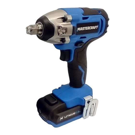
- Page 1 1/2” (13 MM) IMPACT WRENCH 054-7562-2 IMPORTANT: INSTRUCTION Read and understand this instruction manual MANUAL thoroughly before using the product.
- Page 2 headline bars headline bars headline bars continuation tabs continuation tabs continuation tabs notes notes notes warnings warnings warnings...
-
Page 3: Table Of Contents
TABLE OF CONTENTS Technical Specifications Safety Guidelines Key Parts Diagram Operating Instructions Maintenance Troubleshooting Parts List Warranty NOTE: If any parts are missing or damaged, or if you have any questions, please call our toll-free helpline at 1-800-689-9928. SAVE THESE INSTRUCTIONS •... -
Page 4: Technical Specifications
headline bars headline bars headline bars model no. 054-7562-2 | contact us 1-800-689-9928 TECHNICAL SPECIFICATIONS Rated Voltage 20V d.c. No-Load Speed 0–2500 RPM Impact Rate 0–3200 BPM Torque 150 ft-lb Output Driver 1/2” (13 mm) Square continuation tabs continuation tabs continuation tabs Tool Weight (without battery) 2 lb 10 oz (1.19 kg) -
Page 5: Safety Guidelines
SAFETY GUIDELINES: WARNING! Safety symbols in this Instruction Manual are used to flag possible dangers. The safety symbols and their explanations require your full understanding. The safety warnings do not, by themselves, eliminate any danger, nor are they substitutes for proper accident prevention measures. - Page 6 headline bars headline bars headline bars model no. 054-7562-2 | contact us 1-800-689-9928 ELECTRICAL SAFETY • Power tool plugs must match the outlet. Never modify the plug in any way. Do not use any adaptor plugs with earthed (grounded) power tools. Unmodified plugs and matching outlets will reduce risk of electric shock.
- Page 7 POWER TOOL USE AND CARE • Do not force the power tool. Use the correct power tool for your application. The correct power tool will do the job better and safer at the rate for which it was designed. • Do not use the power tool if the switch does not turn it on and off.
- Page 8 headline bars headline bars headline bars model no. 054-7562-2 | contact us 1-800-689-9928 • Do not expose a battery pack or tool to fire or excessive temperature. Exposure to fire or temperature above 130°C (265°F) may cause explosion. • Follow all charging instructions and do not charge the battery pack or tool outside the temperature range specified in the instructions.
- Page 9 Bits, sockets, and tools get hot during operation. Wear gloves when touching them. • Wear ear protection. Exposure to noise can cause hearing loss. • To reduce the risk of electric shock or damage to the charger and battery, use only the Mastercraft batteries and chargers listed. ® BATTERY PACK CHARGER...
-
Page 10: Key Parts Diagram
headline bars headline bars headline bars model no. 054-7562-2 | contact us 1-800-689-9928 PACKAGE CONTENTS: Cordless impact wrench, belt clip and instruction manual. KEY PARTS DIAGRAM continuation tabs continuation tabs continuation tabs notes notes notes warnings warnings warnings Description Description 1/2”... -
Page 11: Operating Instructions
OPERATING INSTRUCTIONS TO ATTACH BATTERY PACK (fig 1) fig 1 1. Lock the variable-speed trigger switch on the Battery- ATTACH impact wrench by placing the direction-of-rotation release selector (forward/centre-lock/reverse) in the centre button position. 2. Align the raised rib on the battery pack with the grooves on the impact wrench, and then attach the battery pack to the impact wrench. - Page 12 headline bars headline bars headline bars model no. 054-7562-2 | contact us 1-800-689-9928 INSTALL THE BELT CLIP (fig 2) fig 2 1. Remove the battery from the tool. 2. Align the rib of the clip with the hole on the base of the cordless impact wrench.
- Page 13 ELECTRIC BRAKE To stop the impact wrench, release the variable-speed trigger switch and allow the tool to come to a complete stop. The electric brake quickly stops the rotation. This feature engages automatically when you release the variable-speed trigger switch. LED WORKLIGHTS (fig 5) fig 5 LED worklights...
- Page 14 headline bars headline bars headline bars model no. 054-7562-2 | contact us 1-800-689-9928 INSTALLING FASTENERS To fasten 1. Start threading the fastener by hand onto or into its threaded counterpart (e.g., nut onto bolt, or bolt into nut or threaded hole). 2.
- Page 15 IMPACTING TIPS The proper fastening torque may differ depending on the type or size of the bolt, the material of the workpiece to be fastened, etc. Practice with various fasteners, noting the length of time required to reach the desired torque. Check the tightness with a hand-torque wrench.
-
Page 16: Maintenance
headline bars headline bars headline bars model no. 054-7562-2 | contact us 1-800-689-9928 MAINTENANCE BEFORE EACH USE 1. Inspect the impact wrench, the variable-speed trigger switch, the battery pack and the accessories for damage. 2. Check for damaged, missing, or worn parts. 3. -
Page 17: Troubleshooting
TROUBLESHOOTING Problem Possible Causes Solution The impact wrench does not The battery is depleted. Charge the battery. work. Socket cannot be installed. Improper socket selection. Use a suitable socket. Be sure the cooling vents are Clean and clear vents. Do The motor is overheating. - Page 18 headline bars headline bars headline bars headline bars headline bars headline bars model no. 054-7562-2 | contact us 1-800-689-9928 EXPLODED VIEW continuation tabs continuation tabs continuation tabs continuation tabs continuation tabs continuation tabs notes notes notes notes notes notes warnings warnings warnings warnings...
- Page 19 No. Part No. Description No. Part No. Description 5610284000 Tapping Screw 3129802000 Rear Cover Front Gear Housing 2826101000 3706708000 Cover Assembly 3129803000 LED Cover 3680212000 Magnetic Shoe Motor and Gear 3129912000 Support 2790464000 Assembly 3129850000 Decorative Cover 2830368000 Electric Assembly 5650501000 Washer 3127732000 F/R Button...
- Page 20 054-7562-2 | contact us 1-800-689-9928 This Mastercraft product is guaranteed for a period of 3 years from the date of original retail purchase against defects in workmanship and materials, except for the following components: a) Component A: Batteries, chargers and carrying case, which are guaranteed for a period of 2 years from the date of original retail purchase against defects in workmanship and materials;...
- Page 21 The provisions contained in this warranty are not intended to limit, modify, take away from, disclaim or exclude any statutory warranties set forth in any applicable provincial or federal legislation. Made in China Imported by Mastercraft Canada Toronto, Canada M4S 2B8...
- Page 22 1/2” (13 MM) DRILL/DRIVER 054-7520-2 IMPORTANT: INSTRUCTION Read and understand this instruction manual MANUAL thoroughly before using the product.
- Page 23 headline bars headline bars headline bars continuation tabs continuation tabs continuation tabs notes notes notes warnings warnings warnings...
-
Page 24: Parts List
TABLE OF CONTENTS Technical Specifications Safety Guidelines Key Parts Diagram Operating Instructions Maintenance Troubleshooting Parts List Warranty NOTE: If any parts are missing or damaged, or if you have any questions, please call our toll-free helpline at 1-800-689-9928. SAVE THESE INSTRUCTIONS •... -
Page 25: Technical Specifications
headline bars headline bars headline bars model no. 054-7520-2 | contact us 1-800-689-9928 TECHNICAL SPECIFICATIONS Rated Voltage 20 V d.c. Chuck Capacity 1/2" (13 mm) No-load Speed 0-400 RPM / 0-1700 RPM Max. Torque 420 in-lb Clutch 24, including drill mode continuation tabs continuation tabs continuation tabs... -
Page 26: Safety Guidelines
SAFETY GUIDELINES: WARNING! Safety symbols in this Instruction Manual are used to flag possible dangers. The safety symbols and their explanations require your full understanding. The safety warnings do not, by themselves, eliminate any danger, nor are they substitutes for proper accident prevention measures. - Page 27 headline bars headline bars headline bars model no. 054-7520-2 | contact us 1-800-689-9928 ELECTRICAL SAFETY • Power tool plugs must match the outlet. Never modify the plug in any way. Do not use any adaptor plugs with earthed (grounded) power tools. Unmodified plugs and matching outlets will reduce risk of electric shock.
- Page 28 POWER TOOL USE AND CARE • Do not force the power tool. Use the correct power tool for your application. The correct power tool will do the job better and safer at the rate for which it was designed. • Do not use the power tool if the switch does not turn it on and off.
- Page 29 headline bars headline bars headline bars model no. 054-7520-2 | contact us 1-800-689-9928 • Follow all charging instructions and do not charge the battery pack or tool outside the temperature range specified in the instructions. Charging improperly or at temperatures outside the specified range may damage the battery and increase the risk of fire.
- Page 30 • Wear ear protectors when using the drill/driver. Exposure to noise can cause hearing loss. • Use protective gloves when removing the bit from the tool, or first allow the bit to cool down. The bit may be hot after prolonged use. •...
- Page 31 054-7520-2 | contact us 1-800-689-9928 WARNING! To reduce the risk of electric shock or damage to the charger and battery, use only the Mastercraft batteries and chargers listed. ® BATTERY PACK CHARGER 054-3124-0...
-
Page 32: Key Parts Diagram
PACKAGE CONTENTS: Cordless drill/driver, 2 screwdriver bits, 1 belt clip, 1 bit holder, and instruction manual KEY PARTS DIAGRAM Description Description Two-speed gearbox switch LED worklight Torque-adjustment ring Magnet Keyless chuck Direction-of-rotation selector Trigger switch Before attempting to use this tool, become familiar with all of its operating features and safety requirements. -
Page 33: Operating Instructions
Improper assembly of the battery pack can cause damage to internal components. WARNING! • Carefully read the Instruction Manuals for your Mastercraft Rechargeable Battery (054-3124-0, 054- ® 7553-4, 054-2434-8, 054-7557-6) and Mastercraft Battery Charger (054-3126-6, 054-7559-2) for safety ®... - Page 34 TURN THE TOOL ON/OFF (fig 2) fig 2 To turn the drill/driver ON, depress the variable- speed trigger switch. To turn it OFF, release the Variable-speed variable-speed trigger switch. trigger switch VARIABLE SPEED (fig 2) Direction- of-rotation The variable-speed trigger switch delivers higher selector speed with increased trigger pressure and lower speed with decreased trigger pressure.
- Page 35 headline bars headline bars headline bars model no. 054-7520-2 | contact us 1-800-689-9928 LED WORKLIGHT (fig 4) fig 4 The LED worklight, located on the base of the cordless drill/driver, will illuminate when the trigger switch is depressed, and will automatically turn worklight off a while after the trigger switch is released.
- Page 36 INSTALL THE BELT CLIP (fig 7 ) fig 7 1. Remove the battery from the tool. 2. Align the rib of the clip with the hole on the base of the drill/driver. Screw 3. Insert the screw (included) and tighten the screw securely with a screwdriver (not included).
- Page 37 headline bars headline bars headline bars model no. 054-7520-2 | contact us 1-800-689-9928 MAGNET STORAGE ON TOP (fig 9) fig 9 The magnet on the top of the drill/driver allows for convenient placement of screws and bits. Magnet continuation tabs continuation tabs continuation tabs ADJUSTABLE TORQUE CLUTCH (fig 10)
- Page 38 INSTALLING A BIT (fig 11, 12) fig 11 1. Lock the trigger switch by placing the direction-of- rotation selector in the OFF (centre) position. 2. Rotate the chuck in the “RELEASE” direction to open RELEASE GRIP the jaws of the chuck. 3.
- Page 39 headline bars headline bars headline bars model no. 054-7520-2 | contact us 1-800-689-9928 GENERAL DRILLING (fig 13) fig 13 1. Check the direction-of-rotation selector for the correct setting (forward or reverse). 2. Use a vise or clamps to secure the material to be drilled to keep it from turning as the drill bit rotates.
- Page 40 DRILLING MODE OPERATION FOR DRILLING IN WOOD, USE TWIST BITS, SPADE BITS, POWER AUGER BITS OR HOLE SAWS. 1. When drilling “through” holes, place a block of wood behind the workpiece to prevent ragged or splintered edges on the back side of the hole. 2.
-
Page 41: Maintenance
headline bars headline bars headline bars model no. 054-7520-2 | contact us 1-800-689-9928 MAINTENANCE BEFORE EACH USE: 1. Inspect the cordless drill/driver, the trigger switch, and the cord for damage. 2. Check for damaged, missing, or worn parts. 3. Check for loose screws, misalignment or binding of moving parts, or any other condition that may affect the operation. -
Page 42: Troubleshooting
TROUBLESHOOTING Problem Possible Causes Solution The cordless drill/driver The battery is depleted. Charge the battery. does not work. The chuck is not opened. Open the chuck. The bit cannot be installed. The bit does not fit the chuck. Use a suitable bit. Be sure cooling vents are free Clean and clear the vents. - Page 43 headline bars headline bars headline bars model no. 054-7520-2 | contact us 1-800-689-9928 EXPLODED VIEW continuation tabs continuation tabs continuation tabs notes notes notes No. Part No. Description No. Part No. Description warnings warnings warnings 5620488000 Screw (L.H.) 5620040000 Screw 3860144000 Chuck 3705301000 Hook 2790452000 Gear Case Assembly...
- Page 44 This Mastercraft product is guaranteed for a period of 3 years from the date of original retail purchase against defects in workmanship and materials, except for the following components: a) Component A: Batteries, chargers and carrying case, which are guaranteed for a period of 2 years from the date of original retail purchase against defects in workmanship and materials;...
- Page 45 The provisions contained in this warranty are not intended to limit, modify, take notes notes notes away from, disclaim or exclude any statutory warranties set forth in any applicable provincial or federal legislation. Made in China Imported by Mastercraft Canada Toronto, Canada M4S 2B8 warnings warnings warnings...
Need help?
Do you have a question about the 7381 and is the answer not in the manual?
Questions and answers