Table of Contents
Advertisement
WARNING:
!
not use with modified
sine wave inverter.
Motor:
Speed:
Impact speed:
Torque:
Square drive:
Weight:
Need Assistance?
Call us on our toll free customer support line:
1-800-689-9928
Technical questions
Replacement parts
Parts missing from package
Imported by Mastercraft Canada Toronto, Canada M4S 2B8
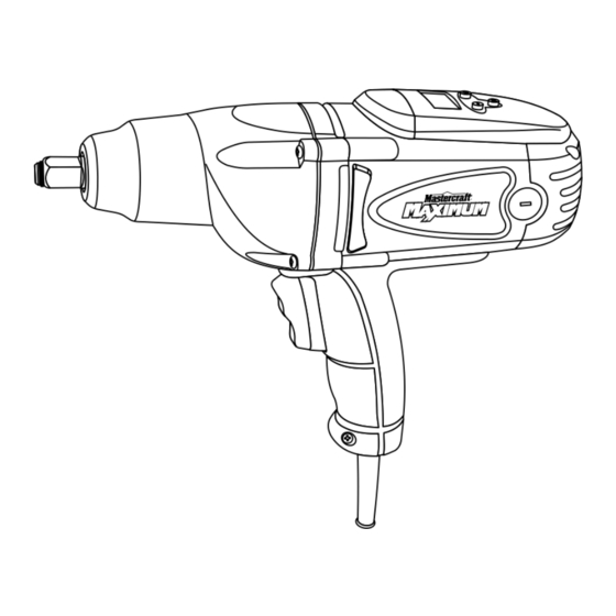
DIGITAL IMPACT WRENCH
Do
PRODUCT SPECIFICATIONS
120 V AC, 60 Hz, 8.5 A
2200 RPM (no load)
3000 BPM (no load)
80–350 ft/lbs
1/2"
8 lb 13 oz (3.6 kg)
054-1265-6
Owner's Manual
Advertisement
Table of Contents

Related Manuals for MasterCraft 054-1265-6


Summary of Contents for MasterCraft 054-1265-6
-
Page 1: Product Specifications
Square drive: Weight: 8 lb 13 oz (3.6 kg) Need Assistance? Call us on our toll free customer support line: 1-800-689-9928 Technical questions Replacement parts Parts missing from package Imported by Mastercraft Canada Toronto, Canada M4S 2B8... -
Page 2: Table Of Contents
TABLE OF CONTENTS Product specifications ………….……………………………………………………. Table of contents ……………………………………………………………………... General safety warnings …………………………………………………………….. 3–4 Eye, ear & lung protection …………………………………………………………… 3–4 Electrical safety ………………………………………………………………………. Power tool safety ……………………………………………………………………... 5–6 General safety rules ………………………………………………………………….. Work area ………………………………………………………………….………….. Electrical safety ………………………………………………………………………. Personal safety ……………………………………………………………………….. -
Page 3: General Safety Warnings
GENERAL SAFETY WARNINGS WARNING: Before using this tool or any of its accessories, read this manual and follow all Safety Rules and Operating Instructions. The important precautions, safeguards and instructions appearing in this manual are not meant to cover all possible situations. It must be understood that common sense and caution are factors which cannot be built into the product. -
Page 4: Electrical Safety
GENERAL SAFETY WARNINGS WEAR A DUST MASK THAT IS DESIGNED TO BE USED WHEN OPERATING A POWER TOOL IN A DUSTY ENVIRONMENT. WARNING: Dust that is created by power sanding, sawing, grinding, drilling, and other construction activities may contain chemicals that are known to cause cancer, birth defects. -
Page 5: Power Tool Safety
POWER TOOL SAFETY WARNING Read all safety warnings When operating a power tool outdoors, and instructions. Failure to follow the use an extension cord suitable for warnings and instructions may result in outdoor use. Use of a cord suitable for electric shock, fire and/or serious injury. -
Page 6: Use And Care Of Power Tools
POWER TOOL SAFETY PERSONAL SAFETY – cont’d Maintain power tools. Check for misalignment or binding of moving Do not overreach. Keep proper footing parts, breakage of parts and any other and balance at all times. This enables condition that may affect the power tool’s operation. -
Page 7: Specific Safety Rules
SPECIFIC SAFETY RULES WARNING: WARNING: Know your impact Always use a torque wrench. Do not plug the tool into the wrench to verify the torque being delivered power source until you have read and each time the impact wrench torque setting understand this Instruction Manual. -
Page 8: Extension Cord Safety
SPECIFIC SAFETY RULES The following table shows the correct size WARNING: This impact wrench is to use according to cord length and the calibrated for tightening standard nuts amperage rating that is listed ton the tool's used on automotive wheel nuts. Using the nameplate. -
Page 9: Symbols
SYMBOLS WARNING: Some of the following symbols may appear on the impact wrench. Study these symbols and learn their meaning. Proper interpretation of these symbols will allow for more efficient and safer operation of this tool. Volts Direct current Amperes No load speed Hertz Alternating or direct... -
Page 10: Know Your Impact Wrench
KNOW YOUR IMPACT WRENCH Torque Torque setting setting LCD buttons ½” square Air vent drive LCD display ON/OFF switch Air vents Motor brush Socket Handle retainer Three position trigger switch ACCESSORIES AVAILABLE ACCESSORIES Before using any accessory, carefully read the instructions or the owner’s manual for WARNING: the accessory. -
Page 11: Contents
CONTENTS CONTENTS Carefully unpack the impact wrench. Compare against the “COMPONENTS” chart below. NOTE: See illustration of contents at right. WARNING: To avoid fire or toxic reaction, never use gasoline, naphtha, acetone, lacquer thinner or similar highly volatile solvents to clean the tool. -
Page 12: Assembly And Operation
ASSEMBLY AND OPERATION INSTALLING IMPACT SOCKETS To operate the impact wrench in the reverse direction, press and hold the WARNING: top part of the switch (3). The socket Use only impact will rotate in a counter clockwise sockets and accessories that are direction to loosen the fastener. -
Page 13: Setting The Torque Value
ASSEMBLY AND OPERATION SETTING THE TORQUE VALUE When tightening fasteners, the preset torque value in the LCD window will flash and the digital torque control will automatically turn the impact wrench OFF as soon as the preset torque is reached. NOTE: The digital torque control will function ONLY when the socket is turning clockwise to tighten the fastener. - Page 14 ASSEMBLY AND OPERATION ASSEMBLY AND OPERATION SETTING THE TORQUE VALUE – cont’d To turn the LCD display OFF, press the torque control button a second time. NOTE: The memory within the digital torque system will “remember” the preset torque value until the torque value is changed.
-
Page 15: Removing Wheel Nuts
ASSEMBLY AND OPERATION REMOVING WHEEL NUTS One of the most common uses for the impact wrench is to remove car wheel nuts for rotating the tires. Car wheel nut removal is used for illustrative purposes. DANGER: Before attempting to remove a car wheel, make sure all jacking, wheel blocking and wheel removal safety procedures illustrated in the Owner’s Manual for your car are... -
Page 16: Tightening Wheel Nuts
ASSEMBLY AND OPERATION ASSEMBLY AND OPERATION REMOVING WHEEL NUTS – cont’d While holding the tool level with the ground and with a firm grasp, squeeze the upper portion of the trigger switch (4). NOTE: Once the nut has been removed, release the trigger. - Page 17 ASSEMBLY AND OPERATION ASSEMBLY AND OPERATION TIGHTENING WHEEL NUTS – cont’d Place the wheel on the wheel studs and thread one wheel nut (1) clockwise onto each wheel stud (Fig. 6). NOTE: Thread each wheel nut at least three full turns onto the wheel stud to make sure the nuts are NOT cross threaded.
-
Page 18: Assembly And Operation
ASSEMBLY AND OPERATION TIGHTENING WHEEL NUTS – cont’d Once all the wheel nuts are tightened to 80 ft/lbs, set the maximum torque value to that which is recommended by the vehicle manufacturer or the fastener manufacturer. Tighten all wheel nuts to the manufacturer’s recommended torque, following the same sequence as noted above. -
Page 19: Maintenance
MAINTENANCE REPLACING CARBON MOTOR BRUSHES The carbon motor brushes will wear down and require replacing. The time intervals between replacements will vary depending upon the torques being achieved and the hours of use. It is recommended that the brushes be checked after each 10 hours of use. - Page 20 MAINTENANCE GENERAL WARNING: When servicing, use only identical replacement parts. Use of any other part may create a hazard or cause product damage. DO NOT use solvents when cleaning plastic parts. Plastics are susceptible to damage from various types of commercial solvents and may be damaged by their use.
-
Page 21: Exploded View
EXPLODED VIEW... -
Page 22: Parts List
PARTS LIST ® WARNING: When servicing, use only Mastercraft replacement parts. The use of any other parts may create a safety hazard or cause damage to the impact wrench. Any attempt to repair or replace electrical parts on this impact wrench may create a safety hazard unless repairs are performed by a qualified technician. - Page 23 PARTS LIST Key # Part # Part Name Quantity 2030110019 Pendulum plate 3150010071 1010180003 Rotor assembly 4010010060 Bearing 608-2RS 3140040001 Bearing Sleeve 2010170017 Magnetism ring 4100050004 Pendulum plate 3150050046 Baffle plate - rear 3150160134 Baffle plate mount 4030010122 Self tapping screw ST3.9X70 1020180003 Stator 2050060140...
-
Page 24: Warranty
5-Year Limited Warranty This Mastercraft® Maximum® product is guaranteed for a period of five (5) years from the date of original retail purchase against defects in workmanship and materials, except for the following components: Component A: Batteries, chargers and carrying cases, which are guaranteed for a period of two (2) years from the date of original retail purchase against defects in workmanship and materials;... - Page 25 Mastercraft® is a superior line of products selected for their workmanship and materials. These products are designed to meet rigorous quality and performance standards, and are approved by our Quality Assurance laboratory.
Need help?
Do you have a question about the 054-1265-6 and is the answer not in the manual?
Questions and answers