
Subscribe to Our Youtube Channel
Related Manuals for Dormakaba 8900 EMR


Summary of Contents for Dormakaba 8900 EMR
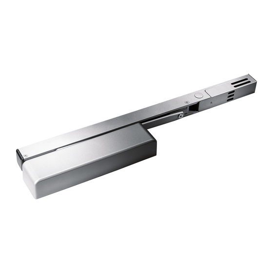
- Page 1 8900 EMR Surface Applied Closer with Detector Installation instructions 08280990 – 03-2020 | EN |...
-
Page 2: Table Of Contents
8900 EMR Installation Instructions Table of Contents Table of contents 1 Technical specifications Maintenance Overview Maintaining the detector Preparation notes Measure and record test voltage Vacuum detector Installation instructions Final steps Installing track to frame Smoke detector testing Install detector... -
Page 3: Technical Specifications
It can be a single installation or part of any of the or more power supplies. When a series of 8900 EMR units are multiple arrangements described above. An auxiliary unit... -
Page 4: Installation Instructions
8900 EMR Installation Instructions Track Detector Slide channel Installation instructions 2.1 Installing track to frame Fig.1 8900T and 8900DE Hinge End cap End cap 8900PT Hinge 2.1.1 8900T and 8900DE: 2.1.2 8900PT: • Install with detector cut-out toward latch edge •... -
Page 5: Install Closer To Door
8900 EMR Installation Instructions Closer 2.4 Install closer to door Fig.4 8900T and 8900DE Left hand door Right hand door 8900PT Right hand door Left hand door 08280990 8900 EMR 03-2020... -
Page 6: Secure Main Arm
8900 EMR Installation Instructions Main arm 2.5 Secure main arm Fig.5 8900T 2.5.1 Attach main arm 6mm hex key to door closer. 2.5.2 Place arm on top Left hand door Right hand door pinion as shown at 45° angle. -
Page 7: Adjustments
8900 EMR Installation Instructions Closing speeds Spring force Adjustments 3.1 Adjust closing speeds: sweep, latch, backcheck, delayed action Fig.7 Backcheck Latch Delayed action Backcheck positioning valve Delayed action Sweep Backcheck intensity Sweep Decrease Sweep & Latch Latch Speed Increase Increase Backcheck &... -
Page 8: Wiring
8900 EMR Installation Instructions Electrical specifications Wiring 4.1 Electrical specifications Fig.9 WIRE THE UNITS ACCORDING TO BUILDING AND SYSTEM REQUIREMENTS. OBSERVE ALL APPLICABLE CODES. Voltage input 24 VDC +10% - 15% 24 VAC +10% - 15% NOTE: 120 volt applications require optional external... -
Page 9: Power Supply 120 Vac, 50/60 Hz
8900 EMR Installation Instructions Wiring: power supply 120 VAC 50/60 Hz Wiring: power supply 24 V AC/DC 4.2 Power supply 120 VAC, 50/60 HZ Fig.10 120 VAC, 50/60 HZ: Connect the 120 VAC incoming voltage wires to the primary wires of the transformer. -
Page 10: Power Supply 24V Ac/Dc With Remote Detectors
8900 EMR Installation Instructions Wiring: power supply 24 V AC/DC with remote detectors 4.4 Power supply 24V AC/DC with remote detectors Fig.12 24V AC/DC with remote detectors: The step down transformer is not used in this connection. Perform wiring connections as illustrated below. -
Page 11: Wire Gauge
8900 EMR Installation Instructions Wiring: wire gauge 4.5 Wire gauge Fig.13 Wire gauge: The maximum wire gauge for wiring the SD-2 detector module is #18 AWG. The method for determining wire gauge is given below. NOTE: A minimum of 20.4 VDC must be supplied to each solenoid in the run. -
Page 12: Detector To Main Solenoid Connection
8900 EMR Installation Instructions Wiring: SD-2 detector Wiring: Solenoid attachment 4.6 SD-2 detector to main solenoid connection Fig.14 Strip approximately 1/4” of plastic insulation from the end of the two solenoid wires supplied. Connect one end each of the electromagnet wires to terminals 6 & 9 of the SD-2 detector as shown. -
Page 13: Detector Interconnection
8900 EMR Installation Instructions Wiring: SD-2 detector 4.9 SD-2 detector interconnection Fig.17 Up to (5) SD-2 detectors, with or without connection to an auxiliary unit or remote area detector may be interconnected. This limitation applies only to interconnected units and assumes a power supply large enough to handle this load if the power supply is common to all units interconnected. -
Page 14: Detector To Remote Area Detector
8900 EMR Installation Instructions Wiring: SD-2 detector 4.10 SD-2 detector to remote area detector Fig.18 CAUTION: A remote open area detector can only be connected to a unit whose trouble relay contacts (#5 & #13) are connected in a circuit for the purpose of obtaining an audible trouble signal in the event of a circuit fault. -
Page 15: Detector To Remote Alarm Indicator Lamp
8900 EMR Installation Instructions Wiring: SD-2 detector Wiring: alarm initiation 4.12 SD-2 detector to remote alarm indicator lamp Fig.20 Connect the positive wire of the remote alarm indicator lamp to terminal #8 of the detector module. Connect the negative terminal of the indicator lamp to terminal #7 of the SD-2 detector. - Page 16 8900 EMR Installation Instructions Wiring: alarm initiation Fig.22 Connections for two (2) SD-2 detectors would consist of detector (1) in figure below connected to detector (3) in the same manner as it is shown connected to detector (2). Detector (2) would be deleted.
-
Page 17: Detector Sensitivity Test (Ulc Requirment Only)
8900 EMR Installation Instructions Wiring: alarm initiation 4.14 SD-2 detector sensitivity test (ULC requirment only) Fig.23 Voltage output terminals are provided to measure the sensitivity of the smoke detector. With power applied to the detector, connect a volt meter to the two test terminals. The normal range is between 1.27 - 3.38 Vdc. -
Page 18: Reset Detector
8900 EMR Installation Instructions Detector Detector cover Closer cover 4.18 Reset detector Fig.27 Turn light pipe clockwise to reset the detector. The LED will go off. Turn the light pipe to the normal position and the unit will resume blinking every second (7) to ten (1) seconds to indicate that it is reset and functioning properly. -
Page 19: Auxiliary Stops
8900 EMR Installation Instructions Auxiliary stops Maintenance 4.21 Auxiliary stops An auxiliary door stop (by others) must be installed to limit the maximum degree of door swing. Failure to do so may result in damage to the unit. 4.22 Unit testing... - Page 20 8900 EMR Installation Instructions Maintenance 5.3 Vacuum detector Fig.32 First, vacuum or blow off any loose debris on the outside of cover. Then remove the detector cover and screen assembly by rotating a flat screwdriver in slot (both sides) and pulling it straight up. Cover may be difficult to remove the first time.
- Page 21 This can be accomplished by burning paper or fabric in a metal can. dormakaba accepts the use of Home Safeguard Smoke Detector Tester (Models 1H and 25S) if, and only if, it is used: with the Model 1490 Accessory.
- Page 22 DORMA USA, Inc. 1 Dorma Drive, Drawer AC Reamstown, PA 17567 T: 717-336-3881 F: 717-336-2106 www.dormakaba.com...
Need help?
Do you have a question about the 8900 EMR and is the answer not in the manual?
Questions and answers