
Related Manuals for Siemens SIMATIC NET RUGGEDCOM RX5000


Summary of Contents for Siemens SIMATIC NET RUGGEDCOM RX5000
- Page 1 Installation Manual SIMATIC NET Rugged Multi Service Platforms RUGGEDCOM RX5000 Edition 01/2021 https://www.siemens.com...
- Page 2 Preface Introduction Installing the Device SIMATIC NET Device Management Rugged Multi Service Platforms RUGGEDCOM RX5000 Modules Technical Specifications Installation Manual Certification 01/2021 C79000-G8976-1058-13...
- Page 3 Note the following: WARNING Siemens products may only be used for the applications described in the catalog and in the relevant technical documentation. If products and components from other manufacturers are used, these must be recommended or approved by Siemens. Proper transport, storage, installation, assembly, commissioning, operation and maintenance are required to ensure that the products operate safely and without any problems.
-
Page 4: Table Of Contents
Accessing Documentation ....................... v Registered Trademarks ......................v Warranty ..........................vi Training ..........................vi Customer Support ........................vi Contacting Siemens ....................... vii Introduction ........................... 1 Feature Highlights ....................1 Description ......................2 Required Tools and Materials ................. 4 Decommissioning and Disposal ................4 Cabling Recommendations .................. - Page 5 Table of Contents Installing/Removing Line Modules ................ 27 Installing/Removing Power Supply Modules ............30 Technical Specifications ...................... 33 Power Supply Specifications ................33 Failsafe Relay Specifications ................33 Operating Environment ..................33 Mechanical Specifications ..................34 Dimension Drawings ................... 34 Certification .........................
-
Page 6: Preface
. To request or inquire about a user document, contact Siemens Customer Support. Registered Trademarks RUGGEDCOM ™ and ROS™ are trademarks of Siemens AG. Linux® is the registered trademark of Linus Torvalds in the United States and other countries. The registered trademark Linux® is used pursuant to a sublicense from LMI, the exclusive licensee of Linus Torvalds, owner of the mark on a world-wide basis. -
Page 7: Warranty
Preface Warranty Warranty Siemens warrants this product for a period of five (5) years from the date of purchase, conditional upon the return to factory for maintenance during the warranty term. This product contains no user-serviceable parts. Attempted service by unauthorized personnel shall render all warranties null and void. -
Page 8: Contacting Siemens
Call a local hotline center to submit a Support Request (SR). To locate a local hotline center, visit https://w3.siemens.com/aspa_app/?lang=en. Mobile App Install the Industry Online Support app by Siemens AG on any Android, Apple iOS or Windows mobile device and be able to: •... - Page 9 Preface Contacting Siemens viii RUGGEDCOM RX5000 Installation Manual, 01/2021, C79000-G8976-1058-13...
-
Page 10: Introduction
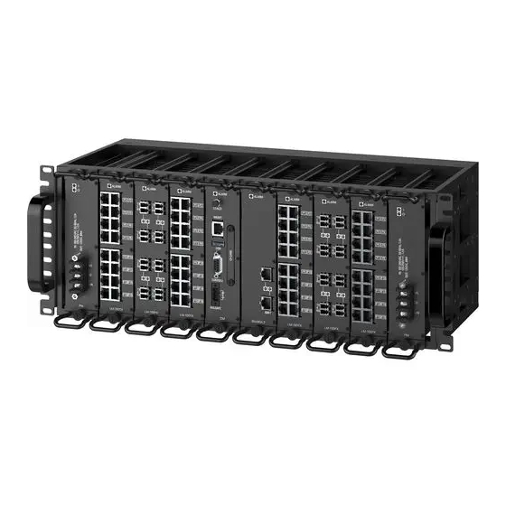
Introduction The RUGGEDCOM RX5000 is a high-port density routing and switching platform, designed to operate in harsh environments.The RUGGEDCOM RX5000 can withstand high levels of electromagnetic interference, radio frequency interference, and a wide temperature range of -40 to 85 °C (-40 to 185 °F). The RUGGEDCOM RX5000 is designed to meet the challenging climatic and environmental demands found in utility, industrial, and military network applications. -
Page 11: Description
Introduction 1.2 Description • Terminal blocks for reliable maintenance-free connections • CSA/UL 62368-1 safety approved to 85 °C (185 °F) Description The RUGGEDCOM RX5000 features various ports, controls and indicator LEDs on individual modules and the front panel for connecting, configuring and troubleshooting the device. - Page 12 Introduction 1.2 Description Power Supply Module Indicator LEDs Alarm Indicator LEDs Utility USB Port Management Ethernet Port Lamp Test/Alarm Cut-Off (LT/ACO) Button RS232 Serial Console Port (DB9) Figure 1.2 Front Panel Power Supply Module Indicator Indicate the status of the power modules. LEDs •...
-
Page 13: Required Tools And Materials
Introduction 1.3 Required Tools and Materials • "Failsafe Relay Specifications (Page 33)" Power Supply Terminal Block A pluggable terminal block. For more information, refer to "Connecting Power (Page 15)". Required Tools and Materials The following tools and materials are required to install the RUGGEDCOM RX5000: Tools/Materials Purpose AC or DC power cord (16 AWG) -
Page 14: 1.5.2 Gigabit Ethernet 1000Base-Tx Cabling Recommendations
Siemens also does not recommend using copper Ethernet ports to interface with devices in the field across distances that could produce high levels of ground potential rise (i.e. greater than 2500 V), during line-to-ground fault conditions. - Page 15 Introduction 1.5.3 Supported Fiber Optic Cables Cable Type Wavelength (nm) Modal Bandwidth Distance (m) (MHz·km) 100Base-FX 1000Base-SX 10GBase-SR OM1 (62.5/125) — 1300 2000 — — OM2 (50/125) — 1300 2000 — — OM3 (50/125) 1500 — 1300 2000 — — OM4 (50/125) 3500 —...
-
Page 16: Installing The Device
This product contains no user-serviceable parts. Attempted service by unauthorized personnel shall render all warranties null and void. Changes or modifications not expressly approved by Siemens AG could invalidate specifications, test results, and agency approvals, and void the user's authority to operate the equipment. -
Page 17: General Procedure
Visually inspect each item in the package for any physical damage. Verify all items are included. IMPORTANT If any item is missing or damaged, contact Siemens for assistance. Mounting the Device The RUGGEDCOM RX5000 is designed for maximum mounting and display flexibility. -
Page 18: Mounting The Device To A Rack
Installing the Device 2.3.1 Mounting the Device to a Rack Forced airflow is not required. However, any increase in airflow will result in a reduction of ambient temperature and improve the long-term reliability of all equipment mounted in the rack space. Note For detailed dimensions of the device with mounting hardware installed, refer to "Dimension Drawings (Page... - Page 19 Installing the Device 2.3.1 Mounting the Device to a Rack To secure the device to a standard 48 cm (19 in) rack, do the following: Make sure the adapters are installed on the correct side of the chassis. • To make the modules and ports accessible, install the adapters at the rear of the chassis •...
-
Page 20: Mounting The Device To A Panel
Installing the Device 2.3.2 Mounting the Device to a Panel Insert the device into the rack. Note Since heat within the device is channeled to the enclosure, it is recommended that 1 rack-unit of space, or 44 mm (1.75 in), be kept empty above the device. This allows a small amount of convectional airflow. - Page 21 Installing the Device 2.3.2 Mounting the Device to a Panel To mount the device to a panel, do the following: Place the device against the panel and align the adapters with the mounting holes. Screw RUGGEDCOM RX5000 Installation Manual, 01/2021, C79000-G8976-1058-13...
-
Page 22: Installing The Chassis Ground Connection
Installing the Device 2.4 Installing the Chassis Ground Connection Adapter Figure 2.2 Panel Mounting Install the supplied screws to secure the adapters to the panel. Make sure the screws are torqued to 2 ± 0.1 N·m (18 ± 1 lbf-in) Installing the Chassis Ground Connection If the ground terminal on the power supply module(s) is not connected to safety Earth, a connection must be provided from the chassis ground terminal on the RUGGEDCOM MX5000 chassis. -
Page 23: Grounding The Device
Installing the Device 2.5 Grounding the Device Secure the grounding cable and external tooth lock washer to the RUGGEDCOM MX5000 with one pan head screw. Torque the screw to 3.4 N·m (30 lbf·in). Note The other end of the grounding cable will be connected to the inside of the enclosure in later steps. -
Page 24: Connecting Power
Installing the Device 2.7 Connecting Power Function Normally Closed Common Ground Normally Open Normally Open Common (Ground) Normally Closed Figure 2.5 Failsafe Alarm Relay Wiring Connecting Power The RUGGEDCOM RX5000 supports dual redundant AC and/or DC power modules that can be installed in any combination. The RUGGEDCOM RX5000 is equipped with a screw-type terminal block, which provides power to both power modules. -
Page 25: 2.7.1 Connecting Ac Power
Installing the Device 2.7.1 Connecting AC Power • For 125/230 VAC rated equipment, an appropriately rated AC circuit breaker must be installed. • For 125/250 VDC rated equipment, an appropriately rated DC circuit breaker must be installed. • It is recommended to provide a separate circuit breaker for each power module module. -
Page 26: 2.7.2 Connecting Dc Power
Installing the Device 2.7.2 Connecting DC Power Connect the positive wire from the power source to the live terminal on the terminal block. Live Terminal Ground Terminal Neutral Terminal Figure 2.6 AC Terminal Block Wiring Connect the negative wire from the power source to the neutral terminal on the terminal block. - Page 27 Installing the Device 2.7.2 Connecting DC Power Connect the positive wire from the power source to the positive terminal on the terminal block. Live Terminal Ground Terminal Neutral Terminal Figure 2.7 DC Terminal Block Wiring Connect the negative wire from the power source to the neutral terminal on the terminal block.
-
Page 28: Device Management
Device Management This section describes how to connect to and manage the device. Connecting to the Device The following describes the various methods for accessing the RUGGEDCOM RX5000 console and Web interfaces on the device. For more detailed instructions, refer to the RUGGEDCOM ROX Configuration Manual for the RUGGEDCOM RX5000. -
Page 29: Configuring The Device
Device Management 3.2 Configuring the Device The management port is a 10/100Base-TX copper Ethernet port with an RJ45 connector. The following is the pin-out for the management port: Name Description Transmit Data+ Transmit Data- Receive Data+ Reserved (Do Not Connect) Figure 3.2 RJ45 Management Port Reserved (Do Not Connect) - Page 30 The following will void the warranty and potentially result in configuration data corruption/loss: • Using a CF card not approved by Siemens for use with this device • Removing the CF card in any scenario other than those described in this section...
- Page 31 Device Management 3.3 Accessing the CompactFlash Card Removing the CF card To remove the CF card from the device, do the following: Make sure the device is powered down. Remove the CF card access panel. Ejector Button CompactFlash Card Access Panel Figure 3.4 Removing the CF Card Press the ejector button to the left of the CF card and then pull the card out.
-
Page 32: Modules
Modules The RUGGEDCOM RX5000 features slots for up to two power modules and eight line modules, which can be used to expand and customize the capabilities of the device to suit specific applications. A variety of modules are available, each featuring a specific type of communication port: copper Ethernet, fiber optic Ethernet, SFP or serial. -
Page 33: Available Modules
Available Modules The following is a list of all power and line modules available for use in the RUGGEDCOM RX5000. For more information about individual modules, refer to the RUGGEDCOM RX5000 Modules Catalog [https://support.industry.siemens.com/cs/ca/ en/view/109748779]. Power Supply Modules RUGGEDCOM RX5000PN PS HI... - Page 34 Modules 4.1 Available Modules Port Type: LC Distance: 2 km (1.2 mi) RUGGEDCOM RX5000PN LM 8FX50 Specifications Article Numbers Speed: 100 Mbps 6GK6050-0AL20-0CU0 (Standard) Interface: FX 6GK6050-0AL20-0CU1 SFP Sockets: 8 (Conformal Coated) RUGGEDCOM RX5000PN LM 4FG50 Specifications Article Numbers Speed: 1000 Mbps 6GK6050-0AL20-0JB0 (Standard) Interface: LX...
- Page 35 Modules 4.1 Available Modules RUGGEDCOM RX5000PN CM01 L3SECL2HW Specifications Article Numbers Layer 3 Security Edition, 6GK6050-0AL30-0EA0 Layer 2 Hardware 6GK6050-0AL30-0EA1 Switch Modules RUGGEDCOM RX5000PN SM02 Specifications Article Numbers Ports: 2 6GK6050-0AL40-0BA0 (Standard) Speed: 1000 Mbps 6GK6050-0AL40-0BA1 Interface: TX (Conformal Coated) Port Type: RJ45 Distance: 100 m (328.1 RUGGEDCOM RX5000PN SM09 Specifications...
-
Page 36: Installing/Removing Line Modules
Modules 4.2 Installing/Removing Line Modules SFP Sockets: 2 6GK6050-0AL40-0UA1 (Conformal Coated) RUGGEDCOM RX5000PN SM61 Specifications Article Numbers Layer 3/88 Gigabit 6GK6050-0AL40-0VA0 Throughput, no uplink (Standard) ports 6GK6050-0AL40-0VA1 (Conformal Coated) RUGGEDCOM RX5000PN SM69 Specifications Article Numbers Layer 3/88 Gigabit 6GK6050-0AL40-0WA0 Throughput, 2x 10G SFP (Standard) + Slots Blank 6GK6050-0AL40-0WA1... - Page 37 Modules 4.2 Installing/Removing Line Modules Ethernet Module Slot (LM1) Ethernet Module Slot (LM2) Ethernet Module Slot (LM3) Control Module (CM) Switch Module (SM) Ethernet Module Slot (LM4) Ethernet Module Slot (LM5) Ethernet Module Slot (LM6) Figure 4.2 Line Modules NOTICE Contamination hazard – risk of equipment damage Prevent the ingress of water, dirts and other debris that may lead to premature equipment failure.
- Page 38 Modules 4.2 Installing/Removing Line Modules Pull the module from the chassis to disconnect it. Chassis Module Screw Figure 4.3 Removing a Module Install a new module or a blank module (to prevent the ingress of dust and dirt). [Optional] If necessary, install the device in the rack. For control and switch modules only, connect power to the device.
-
Page 39: Installing/Removing Power Supply Modules
Modules 4.3 Installing/Removing Power Supply Modules Insert the new module into the slot. Chassis Module Screw Figure 4.4 Installing a Module Tighten the screws to secure the module. [Optional] If necessary, install the device in the rack. For control and switch modules only, connect power to the device. Installing/Removing Power Supply Modules The RUGGEDCOM RX5000 supports dual redundant power supplies that can be installed in any combination. - Page 40 Modules 4.3 Installing/Removing Power Supply Modules Power Supply Module (PS2) Figure 4.5 Power Supply Modules NOTICE Contamination hazard – risk of equipment damage Prevent the ingress of water, dirts and other debris that may lead to premature equipment failure. Always make sure slots are not left empty. Note Power modules are hot swappable.
- Page 41 Modules 4.3 Installing/Removing Power Supply Modules Insert the module into the empty slot. Screws Power Supply Chassis Figure 4.7 Installing a Power Supply Module Hand-tighten the screws to secure the power module to the chassis. Turn on power to the device and confirm the module is receiving and supplying power.
-
Page 42: Technical Specifications
Technical Specifications This section provides important technical specifications related to the device and available modules. Power Supply Specifications Power Input Range Internal Max. Power Supply Type Fuse Rating Consumption HI (125/250 VDC) 88 VDC 300 VDC 6.3 A, 250 V(T) 110 W HI (110/230 VAC) 85 VAC... -
Page 43: Mechanical Specifications
Technical Specifications 5.4 Mechanical Specifications Operating temperature may vary based on the limitations of installed SFPs. Refer to the RUGGEDCOM SFP Transceivers Catalog for SFP temperature ratings. Non-condensing. Mechanical Specifications Weight 14-16 kg (30-35 lbs) Ingress Protection IP40 Chassis Material Aluminum Dimension Drawings Note All dimensions are in millimeters, unless otherwise stated. - Page 44 Technical Specifications 5.5 Dimension Drawings 133.4 117.6 101.6 12.7 16.0 25.4 221.5 311.9 16.0 31.8 Figure 5.1 Overall Dimensions RUGGEDCOM RX5000 Installation Manual, 01/2021, C79000-G8976-1058-13...
- Page 45 Technical Specifications 5.5 Dimension Drawings RUGGEDCOM RX5000 Installation Manual, 01/2021, C79000-G8976-1058-13...
-
Page 46: Certification
UL 62368-1 Information Technology Equipment – Safety – Part 1: General Requirements) 6.1.2 European Commission (EC) This device is declared by Siemens AG to comply with essential requirements and other relevant provisions of the following EC directives: • EN 62368-1 Information Technology Equipment –... -
Page 47: 6.1.3 Fda/Cdrh
Products with Respect to the Restriction of Hazardous Substances The device is marked with a CE marking and can be used throughout the European community. A copy of the CE Declaration of Conformity is available from Siemens AG. For contact information, refer to "Contacting Siemens (Page vii)". -
Page 48: Iso
Support at https://support.industry.siemens.com/cs/ww/en/view/89855782. 6.1.8 RoHS This device is declared by Siemens AG to meet the requirements of the following RoHS (Restriction of Hazardous Substances) directives for the restricted use of certain hazardous substances in electrical and electronic equipment: China RoHS 2 •... -
Page 49: 6.1.9 Other Approvals
Certification 6.1.9 Other Approvals 6.1.9 Other Approvals This device meets the requirements of the following additional standards: • IEEE 1613 IEEE Standard Environmental and Testing Requirements for Communications Networking Devices in Electric Power Substations • IEC 61850-3 Communications Networks and Systems for Power Utility Automation – Part 3: General Requirements •... - Page 50 DC Power ports 5 kV AC Power ports 5 kV Siemens-specified severity levels IEEE 1613 EMC Type Tests Note The RUGGEDCOM RX5000 meets Class 2 requirements for an all-fiber configuration and Class 1 requirements for copper ports. Description...
- Page 51 Certification 6.2 EMC and Environmental Type Tests Description Test Levels HV Impulse Signal ports 5 kV (Fail-Safe Relay output) DC Power ports 5 kV AC Power ports 5 kV Dielectric Strength Signal ports 2 kV DC Power ports 2 kV AC Power ports 2 kV Environmental Type Tests Test...
- Page 52 Further Information Siemens RUGGEDCOM https://www.siemens.com/ruggedcom Industry Online Support (service and support) https://support.industry.siemens.com Industry Mall https://mall.industry.siemens.com Siemens AG Digital Industry Process Automation Postfach 48 48 90026 NÜRNBERG GERMANY...
Need help?
Do you have a question about the SIMATIC NET RUGGEDCOM RX5000 and is the answer not in the manual?
Questions and answers