Atlas RIV938P Operating Instructions Manual
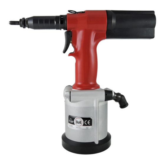
Hydropneumatic tool for rivet nuts from m3 to m10 with oil pressure adjustment
Hide thumbs
Also See for RIV938P:
- Operating instructions manual (48 pages) ,
- Operating instructions manual (51 pages)

Related Manuals for Atlas RIV938P


Summary of Contents for Atlas RIV938P
- Page 1 RIV938P HYDROPNEUMATIC TOOL FOR RIVET NUTS FROM M3 TO M10 WITH OIL PRESSURE ADJUSTMENT OPERATING INSTRUCTIONS QUALITY MANAGEMENT SYSTEM CONFORMING TO ISO 9001:2015 STANDARD CODE 4439600...
- Page 2 Instruction Manual - RIV938P PennEngineering • www.pemnet.com...
- Page 3 RIV938P COMES WITHOUT KITS. KITS MUST BE ORDERED SEPARATELY ACCORDING TO USER NEEDS. FEATURES: RIV938P FEATURES A VALVE-CONTROLLED MOTOR THAT ALLOWS GREATER EFFICIENCY IN SCREWING AND UNSCREWING (6 BARS = SPEED 2250 rpm). 1. Air piston return (without spring). 2. Power piston air outwardly, not through the piston.
- Page 4 Instruction Manual - RIV938P ITEMS AVAILABLE ON REQUEST RIV938P, RIV938, RIV939, RIV939P, RIV939PMAX, RIV941 COMES WITH A SMOOTH BOTTOM (REF. A) YOU CAN SEPARATELY ORDER THE BOTTOM + THE MALE EYEBOLT (KIT REF. (B), CODE 4540500) + THE BALANCER KG. 2/3 (CODE 0523200) MOTOR RUBBER PROTECTION COVER (CODE 4796200) PennEngineering •...
- Page 5 Instruction Manual - RIV938P RIV938P, RIV938, RIV939, RIV941 COMES WITHOUT THE ADJUSTABLE AIR SWITCH, WHICH IS AVAILABLE ON REQUEST (CODE 4280600) Cod. 4280600 REF. CODE DESCRIPTION Fig. 2.5 - A 4280600 COMPLETE ADJUSTABLE AIR SWITCH KIT 4280700 FILTER 4280900 BLOCK...
-
Page 6: Table Of Contents
Instruction Manual - RIV938P CONTENTS GENERAL INFORMATION P. 7 3.1.2 HIGH RESISTANCE SPECIAL KIT FOR M8 WITH FIXED RING NUT SPARE PARTS OF THE MOTOR UNIT (KIT 20) MANUFACTURER ORDERING SPARE PARTS ASSISTANCE CERTIFICATION AND EC MARKING SAFETY P. 29... -
Page 7: General Information
Instruction Manual - RIV938P 1 - GENERAL INFORMATION 1.1 - MANUFACTURER Established in 1973, Rivit S.r.l. produces and distributes Fasteners and Tools (tools for rivets and rivet nuts). With extensive technical experience, the company offers a wide range of products for fastening systems. -
Page 8: Symbols Used
Tool features reduce potential issues caused by the wear and tear of the components, and consequently the tool will last longer and perform better. The technical solutions adopted make the RIV938P more compact and lighter. - Page 9 Instruction Manual - RIV938P TABLE 2.4-A TECHNICAL DATA AND FEATURES AIR WORKING PRESSURE 6 bar MIN – MAX AIR PRESSURE 5 – 7 bar AIR CONSUMPTION PER CYCLE AT 6 BAR 5 litri MAX STROKE 6,5 mm MAX FORCE 19.000 N...
-
Page 10: Nose Assemblies And Standard Accessories
Instruction Manual - RIV938P 2.5 - NOSE ASSEMBLIES AND STANDARD ACCESSORIES The nose assemblies stated below refer to standard tools. A special tool may require special parts, different to those listed. Figure 2.5-A RIV938P- HYDROPNEUMATIC TOOL REF. CODE DESCRIPTION FOR RIVET NUTS WITH OIL PRESSURE... -
Page 11: Accessories On Request
Instruction Manual - RIV938P 2.5.1 - ACCESSORIES ON REQUEST The tool can be supplied with different accessories according to the kind of fastener to be placed. 2.5.1.1 - FOR RIVSERT PLACING: CODE 938P/03 3441100 938P/04 3441200 You must screw the... -
Page 12: Kit938P/03 - Kit For Rivsert M3
Instruction Manual - RIV938P 2.5.1.1.1 KIT938P/03 – KIT FOR RIVSERT M3 Figure 2.5-B REF. CODE DESCRIPTION Fig. 2.5-B 3441100 KIT938P-KIT RIVSERT M3 SOCKET CAP SCREW 2.5.1.1.1.1 KIT938P/03 COMPOSITION Figure 2.5-C TABLE 2.5-A REF. CODE DESCRIPTION 3457500 HEAD WITH RING NUT FOR M3 SCREW... -
Page 13: Kit938P/04 Kit For Rivsert M4
Instruction Manual - RIV938P 2.5.1.1.2 KIT938P/04 – KIT FOR RIVSERT M4 Figure 2.5-D REF. CODE DESCRIPTION Fig. 2.5-D 3441200 KIT938P-KIT RIVSERT M4 SOCKET CAP SCREW 2.5.1.1.2.1 KIT938P/04 COMPOSITION Figure 2.5-E TABLE 2.5-B REF. CODE DESCRIPTION 3470200 HEAD WITH RING NUT FOR M4 SCREW... -
Page 14: Kit938P/05 -Kit For Rivsert M5
Instruction Manual - RIV938P 2.5.1.1.3 KIT938P/05 –KIT FOR RIVSERT M5 Figure 2.5-F REF. CODE DESCRIPTION Fig. 2.5-F 3441300 KIT938P-KIT RIVSERT M5 SOCKET CAP SCREW 2.5.1.1.3.1 KIT938P/05 COMPOSITION Figure 2.5-G TABLE 2.5-C REF. CODE DESCRIPTION 3471800 HEAD WITH RING NUT FOR M5 SCREW... -
Page 15: Kit938P/06 - Kit For Rivsert M6
Instruction Manual - RIV938P 2.5.1.1.4 KIT938P/06 – KIT FOR RIVSERT M6 Figure 2.5-H REF. CODE DESCRIPTION Fig. 2.5-H 3441400 KIT938P-KIT RIVSERT M6 SOCKET CAP SCREW 2.5.1.1.4.1 KIT938P/06 COMPOSITION Figure 2.5-I TABLE 2.5 - D REF. CODE DESCRIPTION 3472200 HEAD WITH RING NUT FOR M6 SCREW... -
Page 16: Kit938P/08 - Kit For Rivsert M8
Instruction Manual - RIV938P 2.5.1.1.5 KIT938P/08 – KIT FOR RIVSERT M8 Figure 2.5-J REF. CODE DESCRIPTION Fig. 2.5-J 3441500 KIT938P-KIT RIVSERT M8 SOCKET CAP SCREW 2.5.1.1.4.1 KIT938P/08 COMPOSITION Figure 2.5-K TABLE 2.5-E REF. CODE DESCRIPTION 3472700 HEAD WITH RING NUT FOR M8 SCREW... -
Page 17: Kit938P/10 - Kit For Rivsert M10
Instruction Manual - RIV938P 2.5.1.1.6 KIT938P/10 – KIT FOR RIVSERT M10 Figure 2.5-N REF. CODE DESCRIPTION Fig. 2.5-N 3441600 KIT938P-KIT RIVSERT M10 SOCKET CAP SCREW 2.5.1.1.6.1 KIT938P/10 COMPOSITION Figure 2.5-O TABLE 2.5-G REF. CODE DESCRIPTION 0329000 HEAD WITH RING NUT FOR M10 SCREW 3473100 SOCKET CAP SCREW M10X6012.9 UNI5931/DIN912... -
Page 18: For Rivbolt Placing
Instruction Manual - RIV938P 2.5.1.2 - FOR RIVBOLT PLACING CODE 938P/04B 3442300 938P/05B 3442400 You must screw the different kits in this position 938P/06B 3442500 938P/08B 3422600 938P/10B 4601900 To install this kit, first remove the quick-kit with spring The user must purchase the following kits separately according to the fastener to be used. -
Page 19: Kit938P/04B - Kit For Rivbolt M4
Instruction Manual - RIV938P 2.5.1.2.1 KIT938P/04B – KIT FOR RIVBOLT M4 Figure 2.5-R REF. CODE DESCRIPTION Fig. 2.5-R 3442300 KIT938P-KIT RIVBOLT M4 SOCKET CAP SCREW 2.5.1.2.1.1 KIT938P/04B COMPOSITION Figure 2.5-S TABLE 2.5-I REF. CODE DESCRIPTION 2561200 HEAD WITH RING NUT FOR M4 RIVBOLT... -
Page 20: Kit938P/05B Kit For Rivbolt M5
Instruction Manual - RIV938P 2.5.1.2.2 KIT938P/05B – KIT FOR RIVBOLT M5 Figure 2.5-T REF. CODE DESCRIPTION Fig. 2.5-T 3442400 KIT938P-KIT RIVBOLT M5 SOCKET CAP SCREW 2.5.1.2.2.1 KIT938P/05B COMPOSITION Figure 2.5-U TABLE 2.5-J REF. CODE DESCRIPTION 2561300 HEAD WITH RING NUT FOR M5 RIVBOLT... -
Page 21: Kit938P/06B - Kit For Rivbolt M6
Instruction Manual - RIV938P 2.5.1.2.3 KIT938P/06B – KIT FOR RIVBOLT M6 Figure 2.5-V REF. CODE DESCRIPTION Fig. 2.5-V 3442500 KIT938P-KIT RIVBOLT M6 SOCKET CAP SCREW 2.5.1.2.3.1 KIT938P/06B COMPOSITION Figure 2.5-W TABLE 2.5-K REF. CODE DESCRIPTION 2561400 HEAD WITH RING NUT FOR M6 RIVBOLT... -
Page 22: Kit938P/08B - Kit For Rivbolt M8
Instruction Manual - RIV938P 2.5.1.2.4 KIT938P/08B – KIT FOR RIVBOLT M8 Figure 2.5-X REF. CODE DESCRIPTION Fig. 2.5-X 3442600 KIT938P-KIT RIVBOLT M8 SOCKET CAP SCREW 2.5.1.2.4.1 KIT938P/08B COMPOSITION Figure 2.5-Y TABLE 2.5-L REF. CODE DESCRIPTION 2700500 HEAD WITH RING NUT FOR M8 RIVBOLT... -
Page 23: Kit938P/10B - Kit For Rivbolt M10
Instruction Manual - RIV938P 2.5.1.2.5 KIT938P/10B – KIT FOR RIVBOLT M10 Figure 2.5-Z REF. CODE DESCRIPTION Fig. 2.5-Z 4601900 KIT938P-KIT RIVBOLT M10 SOCKET CAP SCREW 2.5.1.2.5.1 KIT938P/10B COMPOSITION Figure 2.5-AA TABLE 2.5-M REF. CODE DESCRIPTION 4601700 HEAD WITH RING NUT FOR D.10 RIVBOLT... -
Page 24: Head Extensions
Instruction Manual - RIV938P 2.5.1.3 - HEAD EXTENSIONS M5 12 M6 12 M8 14 Total length of the extension is obtained using the HEAD EXTENSION and the EXTERNAL CONE on the Tool. REF. CODE DESCRIPTION Kit 110/140 4572500 KIT-HEAD EXTENSION D.12X110/140MM FOR RIVSERT M5 4570700 HEAD EXTENSION D.12X110/140 FOR M5 RIVSERT... -
Page 25: Spare Parts
Instruction Manual - RIV938P 3 - SPARE PARTS 3.1 - SPARE PARTS Figure 3.1-A Spare parts PennEngineering • www.pemnet.com... - Page 26 Instruction Manual - RIV938P See Figures 3.1-A TABLE 3.1-A REF. CODE DESCRIPTION REF. CODE DESCRIPTION 4833800 HANDLE CASING 4174200 QUICK KIT WITH SPRING 3539900 OUTER CONE 4177400 GASKET KIT 3 PIECES TOOTHED BLOCKING PISTON – STEM – O-RING KIT 4...
-
Page 27: Quick Kit Complete With Spring Composition
Instruction Manual - RIV938P 3.1.1 - QUICK KIT COMPLETE WITH SPRING Figure 3.1-B REF. CODE DESCRIPTION Fig. 3.1-B 4174200 QUICK KIT WITH SPRING 3.1.1.1 - QUICK KIT COMPLETE WITH SPRING COMPOSITION Figure 3.1-C REF. CODE DESCRIPTION 4172400 TOOTHED BLOCKING RING NUT M3-M10... -
Page 28: Spare Parts Of The Motor Unit (Kit 20)
Instruction Manual - RIV938P 3.2 - SPARE PARTS OF THE MOTOR UNIT (KIT 20) Figure 3.2-A Motor spare parts REF. CODE DESCRIPTION Fig. 3.2-A 3761000 MOTOR UNIT (20) REF. CODE DESCRIPTION REF. CODE DESCRIPTION 3763400 PLANET WHEEL HOLDER 3327300 BEARING... -
Page 29: Safety
Instruction Manual - RIV938P 4 - SAFETY 4.1 - GENERAL WARNINGS The operator should carefully review the information presented in this manual, especially with regards to the safety precautions outlined in this section: • The tool should be used only by trained personnel. -
Page 30: Intended Use
Instruction Manual - RIV938P 4.2 - INTENDED USE The tool is designed exclusively to be used with rivet nuts as described in section 2.1: female type (i.e. Rivit RIVSERT) with thread between M3 and M10, and male rivet nuts (i.e. Rivit RIVBOLT) with thread between M3 and M10. -
Page 31: Installation
Instruction Manual - RIV938P 5 - INSTALLATION 5.1 - TRANSPORT AND HANDLING The tool can be hand carried. It is recommended that you store the tool in its case after use. Damages to the tool caused during transport and/or handling are not covered by WARRANTY. -
Page 32: Operation
Instruction Manual - RIV938P 6 - OPERATION 6.1 - OPERATORS The tool is designed to be used by one operator only. Tool operators must satisfy the requirements stated hereafter (or they must be informed and trained accordingly). They must be aware of the manual herein and of all information relevant to safety: •... -
Page 33: Replacement Of Standard Kit With High Resistance Special One
Instruction Manual - RIV938P 6.2 REPLACEMENT OF STANDARD KIT WITH HIGH RESISTANCE SPECIAL ONE, FOR M8 ONLY (CODE 4508800) WITH FIXED RING NUT: REPLACE TOOTHED RING NUT (1) WITH THE FIXED ONE (2) + (3) (see section 3.1.2) 1,5mm Remove the sleeve (3) : Cod. -
Page 34: Tool Preparation And Screw Replacement
Instruction Manual - RIV938P 6.3 - TOOL PREPARATION AND SCREW REPLACEMENT Warning: Tool setting and screw replacement must be carried out with the tool disconnected from the air supply line. Figure 6.2 - A Between the casing and the nut, there must be a gap of 1.5 mm for... - Page 35 Instruction Manual - RIV938P Figure 6.2-C WARNING! GREEN Pressure (force) must always be regulated as per max. thickness. WHITE Screwing and unscrewing you see three rings (WHITE, GREEN, RED). OIL (FORCE) PRESSURE ADJUSTMENT – SCREW THE IMPORTANT INSERT OIL (FORCE) PRESSURE ADJUSTMENT...
-
Page 36: Information
Instruction Manual - RIV938P 6.4 - INFORMATION The Emergency Unscrewing Button is to be used when the rivet nut gets stuck, or when the inserted rivet nut is not the correct one and it must be changed. EMERGENCY UNSCREWING BUTTON To be used in case the user inserts a wrong rivet nuts. - Page 37 Instruction Manual - RIV938P Figure 6.3-A (1) Rivet nut is stuck. (2) Keep the trigger pressed and rotate to help unblocking. (3) It does not get unblocked. (4) Disconnect the air hose. (5) Insert the Emergency Regulation Pin 53 in the proper holes, unscrewing the tool manually.
-
Page 38: Servicing The Tool
Instruction Manual - RIV938P 7 - SERVICING THE TOOL 7.1 - MAINTENANCE STATUS Maintenance operations must be carried out with the tool stopped and disconnected from the pneumatic supply line. Warnings: • The tool maintenance instructions must be carefully followed. -
Page 39: Filling The Hydraulic Circuit With Oil
Instruction Manual - RIV938P 7.3.1 REFILLING THE HYDRAULIC CIRCUIT WITH OIL Figure 7.3-A The hydraulic circuit needs to be refilled with oil after continuous use, and when you notice a reduction in the tool stroke. Proceed as follows (see Picture 7.3-A): •... -
Page 40: Maintenance Kit On Request
Instruction Manual - RIV938P 7.4 - MAINTENANCE KIT ON REQUEST Follow the instructions below: REF. CODE DESCRIPTION 4461800 MILLED CONE TO SCREW AND UNSCREW THE RING NUT (10) 4461900 BUSH FOR INTRODUCTION OF ROTATING PIN (6) FITTED WITH GASKET THREAD PROTECTOR METAL FERRULE FOR INSERTION OF ROTATING PIN (6) -
Page 41: Fault Diagnosis
Instruction Manual - RIV938P 8 - FAULT DIAGNOSIS 8.1 - POSSIBLE FAULTS O-ring Cod. 4371800 ISSUE REMEDY Traction is not correctly performed. It lacks oil (see section 7.3.1) Unscrewing is not correctly If unscrewing is not correctly performed when inserting the rivet nut in the tie rod, and after performed. - Page 42 Instruction Manual - RIV938P ISSUE REMEDY The transition time from stroke to Open the manostat and pull the piston out (G). unscrewing slows. Grease it and reassemble it. Air leaks from muffler (T). Check the two o-rings (O4) and o-ring (21 code 3235600) which could be worn or broken.
-
Page 43: Fault Diagnosis And Repairs
Instruction Manual - RIV938P 9 - FAULT DIAGNOSIS AND REPAIRS 9.1 - REPAIRS To ensure the operational efficiency and safety of the tool, all repair jobs shall be completed by your local authorized dealer or by the Technical Assistance Service of Rivit S.r.l. (see section 1.2). - Page 44 Instruction Manual - RIV938P ©2013 Rev. 220 PennEngineering • www.pemnet.com...
Need help?
Do you have a question about the RIV938P and is the answer not in the manual?
Questions and answers